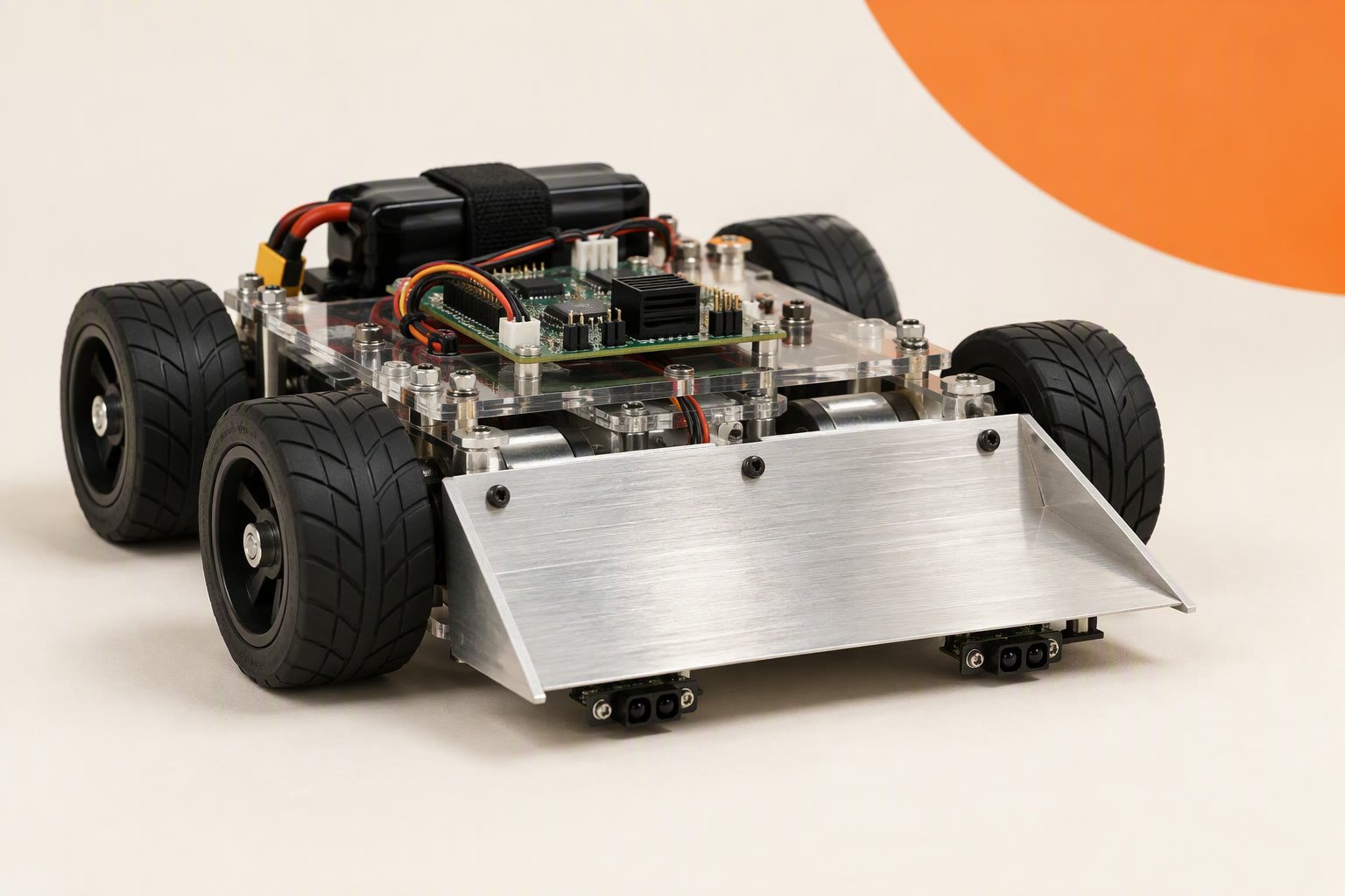
This ₹2,900 sumo robot pairs an Arduino Nano with a TB6612FNG, four TT motors and three reflectance sensors, and it wins or loses on edge logic and traction rather than on the board. The build below gives you a legal, weighable platform, a sensor layout that keeps the robot in the ring, and a test plan that finds the faults before a match does.
Scope: intermediate. You need to solder header pins, drive four motors from one driver and tune an analog threshold. The code is short; the tuning is where the matches are.
Bill of materials
| Part | Qty | Unit | Total |
|---|---|---|---|
| Arduino Nano CH340 | 1 | ₹320 | ₹320 |
| TB6612FNG motor driver | 1 | ₹280 | ₹280 |
| 4WD chassis kit with 4 TT motors and wheels | 1 | ₹750 | ₹750 |
| 2×18650 holder with protected cells | 1 | ₹340 | ₹340 |
| 5 V 2 A buck converter | 1 | ₹190 | ₹190 |
| QTR-1A reflectance sensor | 3 | ₹190 | ₹570 |
| HC-SR04 ultrasonic sensor | 1 | ₹90 | ₹90 |
| Jumper wire set | 1 | ₹80 | ₹80 |
| Switch and foam tape | 1 | ₹60 | ₹60 |
| Silicone traction tape | 1 | ₹100 | ₹100 |
| Standoffs, screws and bumper foam | 1 | ₹120 | ₹120 |
| Parts total | ₹2,900 | ||
Scroll the table sideways to see every column.
Prices checked Oct 2026. Shipping and tools are not included.
Prices are Indian retail ranges in October 2026, before shipping. An Arduino Uno substitutes directly and adds roughly ₹200; the pin numbers in this build are the same on both boards. The cost calculator covers contingency and spares.
What you are building
A sumo robot is a pushing machine with three jobs: stay inside the ring, find the opponent, and move it out. This build uses a four-wheel-drive acrylic chassis because four driven wheels give more traction than two, a TB6612FNG because it wastes less voltage than an L298N, and three analog reflectance sensors because a digital sensor with a potentiometer drifts when the venue lighting changes.
The robot is deliberately low and front-heavy. A foam bumper absorbs the first impact, and the front edge is a shallow scoop rather than a vertical wall. That shape decides whether you slide under the opponent or climb over it.
Read the rules before you cut anything
Sumo rules are local. Two events in the same city can disagree on weight class, size, ring surface and what counts as a legal weapon. Before you buy, get the rulebook and write down the answers to these questions. Building to the strictest plausible version saves a rebuild.
- Weight class: 500 g, 1 kg and 3 kg are common. A 4WD chassis with a 2S pack will usually exceed 500 g, so plan for the 1 kg class or choose lighter parts.
- Size box: many events require the robot to fit inside a square at the start, often 20 × 20 cm. The scoop counts.
- Start procedure: typically a countdown with no movement, sometimes a remote start. A robot that creeps early can be disqualified.
- Ring: diameter, height and border colour. Practice on a surface that matches, or your thresholds will be wrong on match day.
- Allowed hardware: some events ban adhesives, suction, sharp edges and jammers. Reflectance edge sensors are normally fine; check anyway.
Drive and traction: where the push comes from
Pushing force is limited by friction, not by motor torque. The maximum horizontal force before the wheels slip is roughly the friction coefficient times the weight on the driven wheels. Adding mass helps until the class limit; adding grip helps immediately. Silicone tyres, clean rubber and a dust-free ring matter more than another 100 rpm.
Four TT motors do not quadruple the force at each wheel. They spread the same load over four contact patches, which improves traction and resistance to being lifted, but each motor still has its own small stall torque. If you need more push, a lower gear ratio or a larger motor is the real upgrade.
The driver is the next constraint. The TB6612FNG is rated about 1.2 A continuous per channel with short peaks near 3.2 A. Two TT motors on one channel can exceed that in a sustained push, and the driver will thermal-shutdown in the middle of a match. The L298N vs TB6612FNG comparison explains the trade: the L298N tolerates more current per channel but loses 1.4–2 V as heat. Test the worst-case push and feel the driver afterwards.
Voltage is the other compromise. TT motors are usually rated 3–6 V, and a 2S pack through a TB6612 delivers roughly 7 V, closer to 8 V at full charge. That is common in sumo and it is fast, but it shortens brush life. A 6 V motor rail is kinder; it also adds a converter that must pass several amps, which is not cheap.
Pin map
| TB6612FNG | Arduino Nano | Note |
|---|---|---|
| PWMA | D5 | Left pair speed |
| AIN1 / AIN2 | D6 / D7 | Left pair direction |
| PWMB | D10 | Right pair speed |
| BIN1 / BIN2 | D8 / D9 | Right pair direction |
| STBY | D4 | Must be high to enable the driver |
| VCC | 5V | Logic supply only |
| VM | Battery + | 2S pack through the switch |
| GND | Common ground | Battery, Nano and driver |
| QTR left / centre / right | A0 / A1 / A2 | Analog outputs, 5 V supply |
| HC-SR04 TRIG / ECHO | D11 / D12 | Optional opponent sensor |
Edge sensors and the logic that keeps you in the ring
Mount three QTR-1A sensors across the front, 2–4 mm above the surface, with the outer pair wider than the wheel track. If a sensor sits inside the wheel line, the wheel can leave the ring before the robot notices. Point them at the border, not at the opponent.
Read all three every loop. Calibrate by recording the analog value on the ring surface and on the border, then set a threshold roughly halfway between them with margin. The code assumes the border reads brighter than the ring; invert the comparison if yours is dark. Ambient light changes the readings, so calibrate under the venue’s lighting if you can, and recheck before each match.
void loop() {
  int l = analogRead(A0), c = analogRead(A1), r = analogRead(A2);
  bool eL = l > EDGE, eC = c > EDGE, eR = r > EDGE;

  if (eL || eC || eR) {      // border seen: escape before attacking
    escape(eL, eC, eR);
    return;
  }

  int cm = pingCm();          // 0 means no echo
  if (cm > 0 && cm < 60) attack();
  else search();
}
Two rules make this reliable. First, escape by reversing both sides for a fixed time and pivoting away from the sensor that saw the border; do not stop at the edge, because a stopped robot is easy to push out. Second, require two consecutive readings before reacting, so a reflection or a scratch does not trigger a false escape. A centre-only reading means you are perpendicular to the border: reverse straight, then turn.
The HC-SR04 is optional and often disappointing. Its cone is wide, its update is about 50 ms, and a low opponent can slip under the beam. Use it to decide whether to charge or search, never as your only defence. Edge sensing must be fast and independent, which is why it runs first.
The sketch, stage by stage
- Start guard: hold the motors off for the full countdown. Add a switch or a start command, and never move on power-up.
- Edge check: read the three sensors, debounce, and escape if any of them sees the border.
- Search: rotate slowly and sweep the ultrasonic sensor. A slow spin covers more arc than a fast one and keeps the wheels planted.
- Attack: drive straight at the target at full PWM once it is inside about 60 cm, with a short burst of reverse if contact breaks.
- Push: keep both sides at full duty. Reducing PWM during contact reduces your pushing force and lets the other robot recover.
- Failsafe: stop everything if the loop overruns or the battery falls below a safe threshold.
Keep the loop free of delay() calls longer than a few milliseconds. A blocking delay is time you are not watching the edge, and edge detection is the one behaviour that must never wait.
Weight, balance and the front wedge
Weigh the finished robot and measure it inside the size box with the scoop fitted. Move the pack until the robot balances slightly behind the front wheels: too far forward and the rear wheels unload; too far back and the scoop lifts under impact. Velcro and a strap are acceptable; a battery that shifts mid-match is not.
A shallow aluminium or 3D-printed scoop beats a tall vertical plate. It should sit a few millimetres off the surface, span most of the front width, and have no sharp edges. A thin rubber lip improves grip on the opponent without violating the usual no-adhesive rules, but confirm that with your event first.
Test plan
- Weigh and measure: record both numbers with the pack installed and the scoop fitted.
- Sensor-by-sensor: with the robot lifted, slide a card under each sensor and watch the serial values cross the threshold.
- Edge at low speed: drive at 40% PWM toward the border from three angles. Every approach must escape.
- Edge at match speed: repeat at full PWM. This is where momentum carries a robot out.
- Push test: push the robot against a luggage scale and record the force before the wheels slip.
- Stall test: hold the robot still at full throttle for a few seconds and feel the driver. A hot driver will shut down in a match.
- Start compliance: confirm the robot is motionless for the full countdown, every time.
- Three matches: run against a friend’s robot, log the result and the reason for each loss.
What usually goes wrong
| Symptom | Likely cause | Fix |
|---|---|---|
| Drives straight out of the ring | Sensor too high, or threshold set on a different surface | Lower to 2–4 mm; recalibrate on the actual ring |
| Escapes in circles | Only one outer sensor is triggering | Check its wiring and threshold; compare all three raw values |
| Spins instead of driving | One motor pair reversed | Swap that pair’s two leads, not the code |
| Driver shuts down mid-push | Two stalled motors exceed 1.2 A per channel | Add airflow, reduce gearing, or move to a higher-current driver |
| Loses every pushing match | Wheels slipping, or weight too far back | Clean tyres, add traction tape, move the pack forward |
| Climbs over the opponent | Scoop too tall or too steep | Flatten the scoop and lower the centre of mass |
| Resets on impact | Battery contact or brown-out | Strap the pack, shorten power leads, add bulk capacitance |
For the pack and charging rules, read the 18650 battery pack guide and the robot battery guide. The Arduino Uno guide covers the 5 V board family, and the line follower build is the gentlest introduction to reflectance sensors.
Sources and further reading
Arduino, language reference, for analogRead, analogWrite and timing functions. Battery University, BU-205: Types of lithium-ion, for the behaviour of the 2S pack under load.
Last reviewed: October 2026. This build is reviewed against the TB6612FNG and Arduino documentation; it has not been bench-tested by this site. Competition rules vary by event, so check the rulebook you will be judged against.
Push force starts with motor torque; the motor selection guide explains the trade-off with speed.