The MPU6050 is a ₹120–₹250 six-axis IMU that gives you a usable tilt angle in a few lines of code — but its yaw will drift, because a gyroscope alone has no absolute reference. Roll and pitch can be corrected against gravity. Heading cannot, and no filter setting changes that. Here is how to wire it, set the ranges, calibrate and filter.
Key specifications
| Sensors | 3-axis gyro and 3-axis accelerometer |
|---|---|
| Gyro range | ±250 to ±2000 °/s |
| Accel range | ±2 to ±16 g |
| Resolution | 16-bit |
| Interface | I2C up to 400 kHz |
| I2C address | 0x68 (AD0 low) or 0x69 |
| Supply | 2.375–3.46 V (GY-521 board accepts 5 V) |
| Current | about 4 mA |
| Identity register | 0x75 returns 0x68 |
| Extras | temperature sensor, DMP, INT pin |
| Module size | about 21 × 16 mm |
Substitute: MPU9250 when you need a magnetometer for heading, or an ICM-20948 for a more recent part.
What “six axes” actually means
The chip holds a three-axis accelerometer and a three-axis gyroscope. The accelerometer measures acceleration, gravity included, so a stationary board tells you which way is down and therefore how it is tilted. The gyroscope measures angular rate in degrees per second, which you integrate over time to get an angle. There is no magnetometer, so the sensor has no idea where north is.
The two sensors fail in opposite ways, which is why they are used together. The accelerometer is absolute but noisy, and it mistakes every bump and acceleration for a tilt. The gyro is smooth but drifts, because a small error in rate integrates into a growing error in angle.
Wiring and the I2C bus
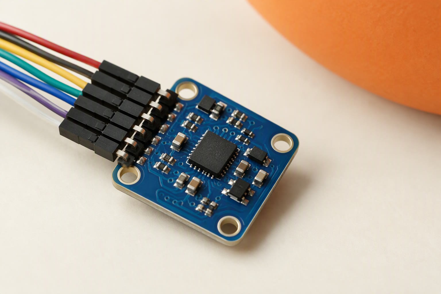
Most modules sold in India are GY-521 boards with eight pins: VCC, GND, SCL, SDA, XDA, XCL, AD0 and INT. Connect VCC and GND, then SCL and SDA to the board’s I2C pins — A5 and A4 on an Uno, GPIO 22 and 21 on an ESP32. The address is 0x68 with AD0 low and 0x69 with it tied high, which is how two of them share a bus. The I2C and SPI guide covers pull-ups and bus length.
The bare chip is a 3.3 V part, but GY-521 boards carry a regulator and are normally used at 5 V; check yours before assuming. Keep the I2C wires short and away from motor cables, and drop to 100 kHz on a long run. XDA and XCL are for an external magnetometer, and INT goes high when new data is ready, which beats polling.
Set the ranges before you read anything
Default ranges suit slow hand gestures, not robots. A gyro at ±250 °/s saturates the moment the chassis turns quickly, and a saturated reading looks like a wrong angle rather than an obvious fault. Pick the range from the motion you expect, then convert raw counts with the datasheet sensitivity.
| Setting | Range | Sensitivity | Use when |
|---|---|---|---|
| Gyro | ±250 °/s | 131 LSB per °/s | Slow tilt sensing, hand gestures |
| Gyro | ±500 °/s | 65.5 LSB per °/s | Small robots, moderate turns |
| Gyro | ±2000 °/s | 16.4 LSB per °/s | Fast spins, impact detection |
| Accel | ±2 g | 16384 LSB per g | Best resolution, gentle motion |
| Accel | ±4 g | 8192 LSB per g | The usual compromise for a robot |
| Accel | ±16 g | 2048 LSB per g | Drop and impact sensing |
The digital low-pass filter, register 0x1A, smooths both sensors. Around 20–40 Hz suits a ground robot: enough to hide motor vibration, not so much that the angle lags the chassis.
Calibrate the gyro, then filter
A gyro at rest does not read zero. The offset is small, but integrating it for a minute turns it into a visible error. Leave the board flat and still, average 500–1000 readings per axis, and subtract those averages from every later reading. Do it in the enclosure the robot will use: the offset shifts with temperature, so a calibration done on a cold desk is wrong once the board warms.
Then fuse the sensors with a complementary filter. Read the accelerometer angle as atan2(ay, az) for roll and atan2(-ax, sqrt(ay*ay + az*az)) for pitch, convert to degrees, and blend at a fixed rate:
angle = 0.98 * (angle + rate * dt) + 0.02 * accelAngle;
At 100 Hz the 0.98 weight trusts the gyro for roughly half a second before the accelerometer pulls the estimate back to vertical. Use the measured dt from millis() rather than assuming a 10 ms loop. This is enough for balancing, tilt control and gesture sensing.
Why yaw still drifts
Roll and pitch have gravity as a reference. Yaw does not. The filter corrects tilt against a known vector, but nothing in the MPU6050 knows which way the robot faces, so a residual bias on the Z axis integrates into heading error forever. Expect a few degrees after a minute or two, more when the board is warm or the chassis vibrates. It is not a bug you can tune out.
There are three honest fixes. Add a magnetometer, the MPU9250 or an external module on XDA/XCL, and accept that motor magnets and battery current distort the field. Add encoders or a line sensor so the robot observes its own motion. Or design so heading does not matter — turn until the line sensor sees the line. Any run that depends on dead-reckoned yaw needs a reset at a known pose.
Mounting, clones and common failures
Mount the board firmly to the chassis, with thin foam or rubber standoffs to take the edge off motor vibration. A floppy mount is worse than a rigid one: it adds its own motion to every reading. Keep the board away from the motor driver and battery leads.
- Check WHO_AM_I. Register 0x75 should return 0x68. Re-marked chips are common, and a different value warns that the part is not what the listing claimed.
- Expect a warm board. The temperature reading is die temperature, not room temperature; typical modules sit a degree or two above ambient.
- Do not hot-plug. Power down before changing I2C wiring; a swapped SDA/SCL is the usual way these boards die.
- Beware old fusion libraries. The on-chip DMP is real, but the Arduino libraries around it are fragile; a 20-line complementary filter is easier to debug.
The gesture-controlled robot uses this tilt pipeline, and the ESP32 guide covers the 3.3 V wiring.
Common questions
Does the MPU6050 work at 5 V?
GY-521 modules include a 3.3 V regulator and are normally used at 5 V. The bare chip is a 3.3 V part, so check the board first.
Why does my angle drift even after calibration?
Roll and pitch drift when the gyro offset is not removed or the loop timing is wrong. Yaw drifts regardless, because there is no magnetometer for an absolute reference.
Can it tell me which way the robot is facing?
No. It has no compass. Heading needs a magnetometer, wheel encoders or an external reference such as a line or wall.
Why is the reading noisy when the motors run?
Vibration and electrical noise. Lower the accelerometer bandwidth, mount the board on thin foam, shorten the I2C wires and keep them off motor cables.
Related: Arduino interrupts and rotary encoders, how to power a robot.
Sources and further reading
- NXP I2C-bus specification (UM10204) — the official reference for addresses, pull-ups and bus timing.
- Arduino language reference —
Wire,atan2()and the timing functions used in the filter loop.
Last reviewed: October 2026. Ranges and sensitivities are from the InvenSense MPU-6050 datasheet; module markings and clone chips vary. Prices are Indian retail ranges.