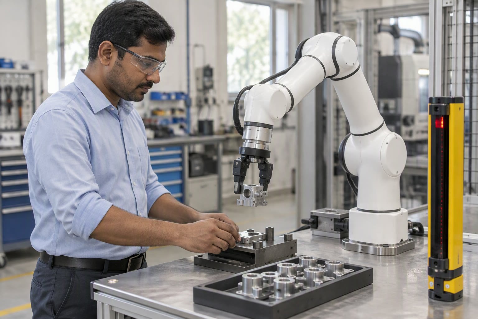
A collaborative robot is not automatically safe. It is a robot whose safety can be demonstrated by measuring force and pressure at the contact point, and that measurement is the part most installations skip.
This guide explains what ISO/TS 15066 requires in practice, how power and force limiting is verified, where hand-guiding and speed-and-separation fit, and the documentation an Indian integrator should hand over.
Four ways to be collaborative
ISO 10218 and ISO/TS 15066 describe four collaborative methods. They are not interchangeable, and a cell may use one or more.
| Method | Principle | Best fit |
|---|---|---|
| Safety-rated monitored stop | Robot stops when a person enters the space | Shared workspace, sequential operation |
| Hand guiding | Operator guides the robot with a handle | Programming, assisted handling |
| Speed and separation monitoring | Robot slows or stops as a person approaches | Larger shared areas, mobile or wide cells |
| Power and force limiting | Contact is permitted but limited to safe force and pressure | Close collaboration, hand-over tasks |
What power and force limiting really means
The idea is that if the robot touches a person, the contact force and pressure must stay below limits that are unlikely to cause injury. ISO/TS 15066 provides body-region-specific values, with lower limits for the face and neck and higher limits for the back and hands.
Two numbers matter. Quasi-static contact is a slow squeeze, where the person is trapped between the robot and a surface. Transient contact is an impact, where the robot strikes and rebounds. Transient limits are higher because the energy is brief, but they assume the contact is momentary.
The practical consequence: a cobot pressing a part against a fixture while an operator’s hand is in the way is a quasi-static event, and the force limit is much lower than the marketing examples suggest.
How to verify it
Verification requires measurement, not calculation alone. The usual method is a force and pressure measurement device at the contact point, with the robot running its actual program at its actual speed and payload.
- Identify contact points. Tool tip, part edges, elbows, and any surface that could contact a person.
- Identify body regions. Which parts of a person could be contacted at each point, and in which posture.
- Measure. Run the program, measure force and pressure at each contact scenario, compare against the limits for that body region.
- Adjust. Reduce speed, add padding, change the tool shape, or add a safety-rated stop where limits cannot be met.
- Document. Record the measurements, the program version, the payload and the tooling. This is the evidence an auditor or insurer will ask for.
The tool is usually the problem
A cobot arm may be certified to a low force, but the gripper is not. A sharp machined edge, a protruding bolt or a hard plastic finger concentrates force into a small area, and pressure is force divided by area. A 40 N force on a 1 cm² edge is 4 MPa, far above any body-region limit.
Design the tool for contact: rounded edges, compliant covers, no exposed fasteners, and a shape that spreads load. Then measure again with the tool fitted. A cell that passes on the bare arm and fails with the tool is a common and entirely avoidable finding.
Tool design principles overlap with those in the gripper design guide, with safety as an additional constraint.
Where cobot cells still need guarding
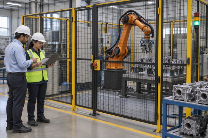
Collaborative operation does not remove the need for a risk assessment, and it does not mean a cell can run without any safeguarding. If the robot carries a sharp blade, a hot tool, or a heavy part, the risk assessment will identify hazards that force and pressure limits cannot address.
In practice, most Indian cobot installations end up with a hybrid: collaborative operation in the load/unload zone, and a fence or light curtain around the rest. That is normal and correct, not a failure of the concept.
The overarching framework is in the robot safety standards guide, and the machinery risk assessment process is the same one used for any machine.
Speed and separation monitoring in practice
This method uses a safety scanner or vision system to measure the distance to a person and slows the robot as they approach. It allows a larger shared space than a fixed fence, but it depends on response time: the robot must be able to stop before contact, which means the separation distance must account for scanner latency, controller latency and stopping distance.
At 1 m/s with a 0.3 s total response and 0.2 m stopping distance, the minimum protective distance is 0.5 m before any safety margin. Reduce the speed and the distance shrinks. That relationship is why many collaborative cells run slower than the robot’s maximum, and why the cycle time in the brochure is rarely achievable.
Documentation handover
Ask for a package, not a certificate. A defensible cobot installation includes: the risk assessment, the force and pressure measurement report with program version, the validation of safety functions, the tool drawing, the operating procedure, and the training record for operators.
If the integrator cannot produce the measurement report, the cell is collaborative by assertion rather than by evidence. That distinction matters the first time someone is injured or an auditor asks a question.
A realistic view of the timeline
A simple cobot cell can be mechanically complete in a week and still take three to four weeks to validate properly, because measurement and adjustment is iterative. Budget that time. Cells rushed to production without measurement are the ones that get restricted by the safety officer six months later, at which point the promised cycle time disappears.
The same discipline applies to conventional cells; the difference is that a cobot’s entire justification rests on the safety argument, so the evidence has to be better.
Is a cobot safe without a fence?
Only if the risk assessment shows all hazards are addressed. Power and force limiting can allow contact, but sharp tools, hot parts and trapping hazards may still require guarding. Many installations use collaborative operation in one zone and guarding elsewhere.
What is ISO/TS 15066?
It is the technical specification that accompanies ISO 10218 and sets out how collaborative operation is implemented, including body-region-specific force and pressure limits for quasi-static and transient contact.
How is power and force limiting verified?
By measuring force and pressure at the actual contact points with the real tool, payload and program, then comparing against the limits for the body regions that could be contacted. The results and program version must be documented.
Why do cobot cells fail force limits?
Usually because of the end effector. Sharp edges, exposed fasteners and small contact areas concentrate force into high pressure. Rounded, compliant tool design and re-measurement with the tool fitted are the fix.
Does collaborative operation reduce cycle time?
Often it does, because safety functions such as speed and separation monitoring require the robot to slow down as people approach. The brochure cycle time assumes ideal conditions that are rarely achieved in shared spaces.
Sources and further reading
- ISO 10218-1 — safety requirements for industrial robots.
- ISO 10218-2 — robot systems and integration.
- ISO/TS 15066 — collaborative robots, safety requirements.
- UK HSE — machinery risk assessment guidance.