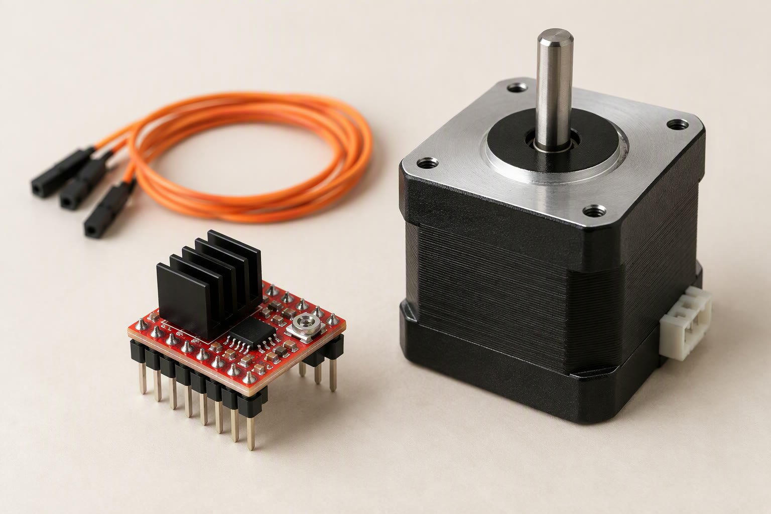
The A4988 is a ₹120–₹250 stepper driver module that turns two GPIO pins into precise motor motion — provided you set its current limit before the first move. It will happily supply more current than its own package can survive, which is why so many of these boards die on day one.
Key specifications
| Motor supply | 8-35 V |
|---|---|
| Logic supply | 3-5.5 V |
| Max current | 2 A peak per coil, about 1 A continuous without cooling |
| Microstepping | full, 1/2, 1/4, 1/8, 1/16 |
| Control | STEP and DIR pulses |
| Current limit | I = Vref / (8 x Rs) |
| Sense resistors | 0.05 ohm (R050) or 0.1 ohm (R100) on clones |
| Step frequency | up to about 200 kHz |
| Protection | thermal shutdown, under-voltage lockout |
| Size | about 15 x 20 mm |
Substitute: A DRV8825 for more current, or a TMC2209 for quiet motion.
What the module actually does
The A4988 chip is a microstepping translator and dual H-bridge. Your microcontroller sends a pulse on STEP and a level on DIR; the chip handles the winding sequence, current regulation and microstep interpolation. Enable, sleep, reset and three microstep-select pins are the rest of the interface. It has no SPI or UART, no stall detection and no configuration memory — every setting is a pin or a trimpot.
The module adds a heatsink pad, a small potentiometer for current limit, and screw terminals. The chip itself is rated to 35 V and 2 A peak per coil, but the module, the heatsink and your airflow decide what you can actually use. Without a heatsink, plan on about 1 A continuous; with a heatsink and moving air, up to roughly 1.5–2 A for short periods.
Set the current limit before anything else
The A4988 limits current by comparing the voltage on its Vref pin with the voltage across two sense resistors. The formula is I = Vref / (8 × Rs), where Rs is the value printed on the small resistors next to the chip. Measure Vref between the Vref test point (or the potentiometer wiper) and GND, with the motor disconnected and logic power applied.
| Sense resistor marking | Resistance | Current per volt of Vref | Vref for 1 A |
|---|---|---|---|
| R050 | 0.05 Ω | 2.5 A/V | 0.40 V |
| R100 | 0.10 Ω | 1.25 A/V | 0.80 V |
| R068 | 0.068 Ω | about 1.84 A/V | 0.54 V |
Pololu’s original board uses 0.05 Ω resistors, so many online guides quote “Vref × 2.5 = current”. Clone boards frequently use 0.1 Ω parts, where the same Vref gives half the current. Read the marking instead of trusting the guide. Set the limit to about 70–80% of the motor’s rated phase current: a 1.7 A NEMA 17 should be run at roughly 1.2–1.4 A on this driver, which is already near its thermal limit.
- Adjust with a small screwdriver and the board powered, but the motor disconnected — a slipping probe shorting Vref to the supply kills the chip.
- Never unplug the motor while the driver is powered. The collapsing coil produces a spike that destroys the output stage.
- Check the heatsink. The self-adhesive pad must be fully in contact and the fins vertical so air can move through them.
Microstepping and steps per revolution
The three MS pins select the microstep resolution. Most modules have internal pull-downs, so leaving all three unconnected gives full-step mode. A 1.8° motor has 200 full steps per revolution; each microstep divides that further.
| MS1 | MS2 | MS3 | Resolution | Steps per revolution |
|---|---|---|---|---|
| L | L | L | Full step | 200 |
| H | L | L | 1/2 | 400 |
| L | H | L | 1/4 | 800 |
| H | H | L | 1/8 | 1600 |
| H | H | H | 1/16 | 3200 |
Microstepping smooths motion and reduces resonance; it does not increase holding torque. At 1/16 the torque per microstep is small and the motor can lose position under a sudden load. For a robot arm, 1/8 or 1/16 with acceleration is usually right. For a conveyor or a lead screw, 1/4 is often enough.
Wiring and the pins people get wrong
| Pin | Connect to | Notes |
|---|---|---|
| VMOT | Motor supply, 8–35 V | Add a 100 µF electrolytic across VMOT and GND close to the board |
| GND | Common ground | Logic and motor ground must meet |
| VDD | 3.3 V or 5 V logic | Do not power from VMOT |
| STEP | Any GPIO | One pulse = one microstep; minimum pulse about 1 µs |
| DIR | Any GPIO | Level sets direction; change it while STEP is idle |
| ENABLE | GND or leave open | Active low; pull high to disable the outputs |
| SLEEP / RESET | Tie together | Floating RESET holds the chip off; tie both to VDD if unused |
| 1A, 1B, 2A, 2B | Motor coils | Pair the coils with a multimeter before connecting |
The most common wiring error is leaving RESET floating. The second is connecting the two motor coils in the wrong pairs, which makes the motor buzz and hold weakly instead of turning. With the motor unplugged, measure resistance: the two wires of one coil read a few ohms, and the pairs read open circuit to each other.
Code: step, direction and acceleration
Raw digitalWrite pulses work for testing, but a real mechanism needs acceleration. The AccelStepper library handles the ramp and keeps the step timing off your main loop.
#include <AccelStepper.h>

const uint8_t STEP_PIN = 3;
const uint8_t DIR_PIN  = 4;

// 1 = driver with step and direction inputs
AccelStepper stepper(AccelStepper::DRIVER, STEP_PIN, DIR_PIN);

void setup() {
  stepper.setMaxSpeed(800);       // steps per second
  stepper.setAcceleration(400);   // steps per second squared
}

void loop() {
  stepper.moveTo(3200);           // one revolution at 1/16 microstep
  stepper.runToPosition();
  delay(500);
  stepper.moveTo(0);
  stepper.runToPosition();
  delay(500);
}
At 1/16 microstep, 3200 steps is one revolution of a 1.8° motor. If the motor stalls or skips, lower the acceleration first; if it still skips at low speed, the current limit is too low or the supply is sagging.
A4988, DRV8825 or TMC2209?
| Driver | Motor supply | Current | Microsteps | Best for |
|---|---|---|---|---|
| A4988 | 8–35 V | about 1 A continuous, 2 A peak | up to 1/16 | Cheap, simple, well documented |
| DRV8825 | 8.2–45 V | about 1.5 A continuous, 2.5 A peak | up to 1/32 | Higher voltage and current, same footprint |
| TMC2209 | 4.75–29 V | 1.4 A RMS, 2 A peak | up to 1/256 | Quiet operation, UART tuning, StallGuard |
The stepper motor guide covers coil identification, torque curves and the difference between a stepper and a geared DC motor. If the mechanism is a wheeled robot rather than a positioning axis, a TB6612FNG or L298N driving DC gear motors is usually simpler and faster.
Common questions
Why does my A4988 get hot immediately?
The current limit is too high for the heatsink and airflow, or the motor is wired in the wrong coil pairs. Set Vref from the sense-resistor marking, fit the heatsink with its pad, and add airflow before running long moves.
Why does the motor vibrate but not turn?
The coil pairs are wrong, one coil is open, or the step pulses are too fast for the load. Check coil resistance with the driver disconnected and start at a low speed with acceleration enabled.
Can I power the A4988 logic from the motor supply?
No. VDD takes 3–5.5 V logic; VMOT takes 8–35 V. Feeding 12 V into VDD destroys the chip.
Do I need the ENABLE pin?
Usually not. It is active low and the outputs are enabled when it is low or floating. Connect it to a GPIO only if you want to disable the driver in software.
Can I run a 1.7 A NEMA 17 at full current on an A4988?
Not continuously without serious cooling. Limit it to about 1–1.4 A, or use a DRV8825 or TMC2209 with a better thermal path.
Related: Arduino Uno, stepper motor with Arduino, servo vs DC motor vs stepper.
Sources and further reading
- Allegro A4988 product page — datasheet, current ratings and thermal data.
- Pololu A4988 carrier — the reference board and its current-limit instructions.
- AccelStepper library — acceleration and multi-motor examples.
Last reviewed: October 2026. Ratings are the commonly published figures for A4988 modules; clone components vary. Prices are Indian retail ranges. Not bench-tested by this site.