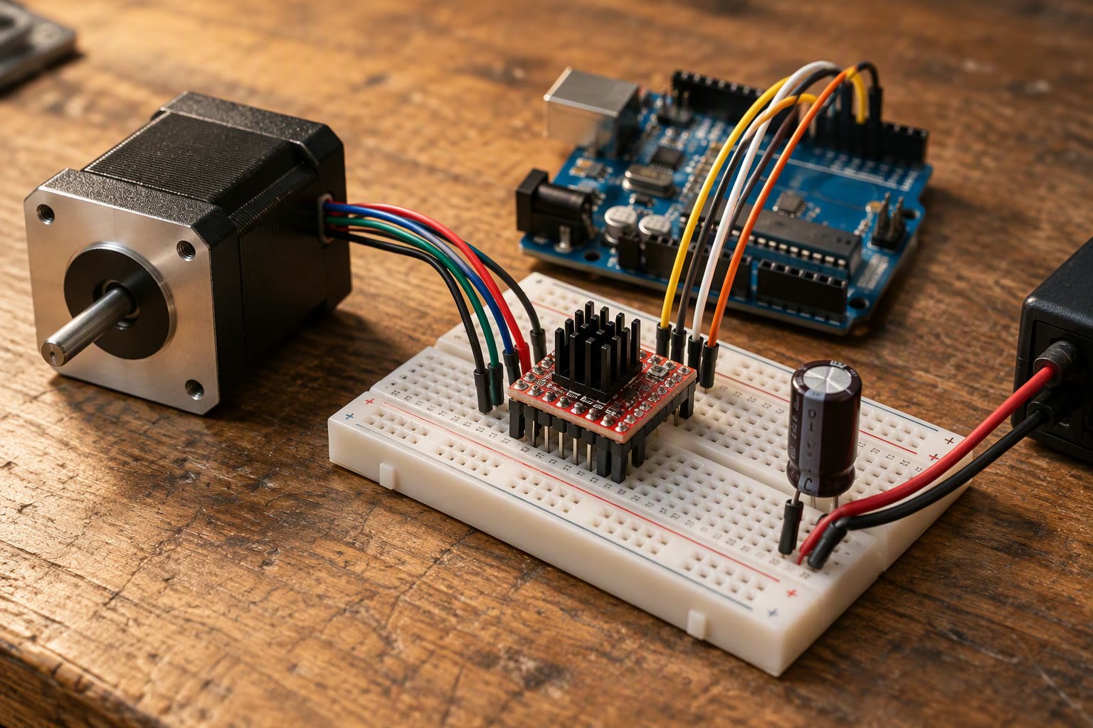
Match the motor to its driver before you write code: a unipolar 28BYJ-48 runs from a ULN2003 board on 5 V, while a bipolar NEMA 17 needs an A4988 or DRV8825 with the current limit set from Vref. The same Arduino library drives both, but the wiring, supply voltage and current setting decide whether the motor turns or just buzzes.
Scope: beginner to intermediate. A multimeter and one multiplication are enough, and getting it wrong overheats the motor.
Unipolar and bipolar: what the wires tell you
A unipolar motor brings out a centre tap on each coil, so it has five or six wires. The driver energises half a coil at a time and current always flows the same way, which is why a darlington array can drive it. The cost is less torque.
The 28BYJ-48 is the cheap example: 5 V, five wires and a plastic gearbox. Its step angle is quoted as 5.625°/64, about 0.088° at the output shaft and roughly 4,096 half-steps per output revolution on paper. The real gear ratio is often 1:63.68, so treat that as approximate.
A bipolar motor has four wires and no centre taps. The driver reverses current through each full coil, so it needs an H-bridge, which gives more torque and better high-speed behaviour. A six-wire motor can run as bipolar by leaving the centre taps unconnected; an eight-wire motor can be wired in series for torque or parallel for speed.
Identify pairs with a multimeter on continuity: a coil reads a few ohms, wires from different coils read open, and a six-wire centre tap reads about half the full-coil resistance.
ULN2003 or A4988/DRV8825?
The ULN2003 is a darlington array, not a current-controlled driver. It sinks current through whichever coil the Arduino selects and does not measure it. That suits a 28BYJ-48 at 5 V, whose current is set by its own resistance, and it cannot drive a bipolar motor.
The A4988 and DRV8825 are chopper drivers. They switch the supply at high frequency and regulate coil current to a value you set, so a 12 V supply can drive a 2 V coil without burning it. The A4988 is cheaper; the DRV8825 adds 1/32 microstepping and a higher voltage rating.
| Driver | Motor type | Motor supply | Current setting | Microstepping | Typical use |
|---|---|---|---|---|---|
| ULN2003 board | Unipolar, 5 or 6 wire | 5 V | None; coil resistance sets it | Full or half step only | 28BYJ-48 and small 5 V motors |
| A4988 | Bipolar, 4 wire | 8–35 V | Vref; about 1 A per coil without a heatsink, 1.5 A with one | Up to 1/16 | Small NEMA 17 |
| DRV8825 | Bipolar, 4 wire | 8.2–45 V | Vref; about 1.5 A per coil without a heatsink, 2.2 A with one | Up to 1/32 | NEMA 17 with headroom |
Wiring the driver to an Arduino
VMOT takes the motor voltage and needs a 100 µF electrolytic across VMOT and GND. VDD takes 5 V from the Arduino; all grounds join. Never plug or unplug a motor while VMOT is on.
| A4988 pin | Connects to | Note |
|---|---|---|
| VMOT, GND | Motor supply, 8–35 V | 100 µF across the pair |
| VDD, GND | Arduino 5V, GND | Logic supply |
| 1A, 1B | Coil A | Pair from the multimeter test |
| 2A, 2B | Coil B | Do not mix coil wires |
| STEP | D3 | One pulse per microstep |
| DIR | D2 | Set before the pulse |
| EN | D4 | Active low |
| MS1, MS2, MS3 | 5V or GND | Table below |
| RESET, SLEEP | Tied together to 5V | Floating pins disable the driver |
Setting the current limit with Vref
The driver limits coil current by comparing a sense voltage to Vref. The formula depends on the sense resistors next to the chip; read their marking before trusting a calculator.
For the A4988 the limit is Vref ÷ (8 × Rs). With 0.05 Ω sense resistors that is Vref ÷ 0.4, so Vref = 0.4 × current and a 1 A limit needs 0.4 V. For the DRV8825 the limit is Vref ÷ (5 × Rs). With 0.1 Ω resistors, Vref = 0.5 × current, so 1 A needs 0.5 V.
Clones vary. A board marked R050 has 0.05 Ω, R068 has 0.068 Ω and R100 has 0.1 Ω. Using the wrong value is the commonest way to set a driver to twice the intended current. If the marking is unreadable, measure the resistors unpowered.
Power VMOT and VDD, stop the step pulses, and measure Vref to GND. Turn the pot slowly; a small movement changes the current a lot. Set the limit to the motor’s rated current. A 1.5 A NEMA 17 on an A4988 without a heatsink should run at 1 A, the carrier’s continuous rating; the DRV8825 also needs its heatsink at 1.5 A.
A heatsink is not decoration. The chip shuts down when it overheats, which looks like a motor that stops after a few minutes and recovers on its own. Repeated shutdowns mean too much current or too little cooling, not a current limit.
Microstepping: what it buys
Full step energises one coil pattern at a time. Microstepping drives both coils with sine and cosine currents, so the rotor settles between full-step positions. Motion is smoother and quieter, but holding torque is roughly the same and each microstep has less torque.
| Microstep | A4988 MS1/MS2/MS3 | DRV8825 MS1/MS2/MS3 | Steps per revolution, 1.8° motor |
|---|---|---|---|
| Full | L L L | L L L | 200 |
| 1/2 | H L L | H L L | 400 |
| 1/4 | L H L | L H L | 800 |
| 1/8 | H H L | H H L | 1,600 |
| 1/16 | H H H | L L H | 3,200 |
| 1/32 | Not available | H L H | 6,400 |
More microsteps is not automatically better. At 1/32 the Arduino must produce twice as many pulses, and friction can absorb the small torque per microstep. Use 1/16 for a first build.
Code with AccelStepper
#include <AccelStepper.h>

const int STEP_PIN = 3, DIR_PIN = 2, EN_PIN = 4;
const long STEPS_PER_REV = 3200;      // 200 full steps x 1/16
AccelStepper stepper(AccelStepper::DRIVER, STEP_PIN, DIR_PIN);

void setup() {
  pinMode(EN_PIN, OUTPUT);
  digitalWrite(EN_PIN, LOW);          // active low
  stepper.setMaxSpeed(1600);          // steps per second, about 30 rpm
  stepper.setAcceleration(800);       // steps per second squared
  stepper.moveTo(5 * STEPS_PER_REV);
}

void loop() {
  if (stepper.distanceToGo() == 0) {
    stepper.moveTo(stepper.currentPosition() == 0 ? 5 * STEPS_PER_REV : 0);
  }
  stepper.run();
}
run() must be called often; it decides whether a step is due. A delay() stalls the motor. For a second motor, call run() on both every loop, or use MultiStepper. The sketch has no homing: position zero is wherever the motor started, and a real axis needs a limit switch.
Why steppers miss steps
- Current too low. The motor buzzes or stalls under a light load while the driver stays cool. Raise Vref.
- Current too high. Motor and driver run hot and the driver shuts down after a few minutes. Lower Vref and fit the heatsink.
- Acceleration too high. The motor skips at the start of a move. Halve the acceleration.
- Speed beyond the torque curve. Stepper torque falls as step rate rises. A motor that lifts at 200 steps/s may stall at 2,000.
- Supply sag. An A4988 needs at least 8 V at VMOT; a 9 V battery under load is not a supply.
- Resonance. A vibration at one speed. Microstepping or a different acceleration profile moves it.
- Mechanics. A misaligned coupling, a tight belt or a binding lead screw asks for more torque than the setting allows.
- Wiring and timing. Coils paired wrongly, a STEP pulse shorter than 1 µs, DIR changed during a pulse, or a hot-plugged motor.
When a stepper beats a servo
A stepper is open loop, and that is its advantage. It moves a fixed number of steps, holds position with current, and rotates continuously without a 180° limit. There is no potentiometer to wear out and no control loop to tune. For a camera slider, a linear stage, a turret or a printer axis, that repeatability is worth the noise and the holding current.
A servo is closed loop inside its case, cheap, fast and simple for a joint between two angles. It cannot rotate continuously without modification, its gears wear, and it buzzes while holding a load. If the job is “move to 45° and stay there”, a servo wins. If the job is “advance exactly 20 mm, two hundred times”, a stepper wins. The catch is that a stepper never knows it missed a step: homing, a limit switch or an encoder is the only way to recover position. The encoder guide covers the counting.
Power is the other catch. A NEMA 17 rated 1.5 A per phase can draw around 3 A with both coils energised, even at rest. The power guide covers supply sizing, the battery guide explains why a small pack will not run one for long, and the actuator comparison puts the three side by side.
The A4988 driver guide covers Vref, microstepping and the wiring mistakes that kill modules.
For motion that has to travel in a straight line, compare linear actuator types before sizing a motor.
Steppers lose torque at speed, which is why the gearbox choice matters as much as the driver.
Choosing the motor is half the job; see NEMA 17 vs NEMA 23 for torque, drivers and cost.
If the motor buzzes or loses position, work through stepper motor missing steps before changing the library or the code.
The driver matters as much as the motor; our stepper driver comparison covers current limits and wiring.
Step rates that outrun an Arduino are one reason builders move to an STM32.
Sources and further reading
- Arduino language reference for timing and the integer types used for step counts.
- Arduino Servo library for the angle-command model this article compares against.
- Battery University: types of lithium-ion for why a pack sags under a stepper’s holding current.
Last reviewed: October 2026. Current-limit formulas and ratings are checked against the A4988 and DRV8825 datasheets and common Pololu-style board documentation; clone boards can use different sense resistors, so read the marking. Not bench-tested by this site.