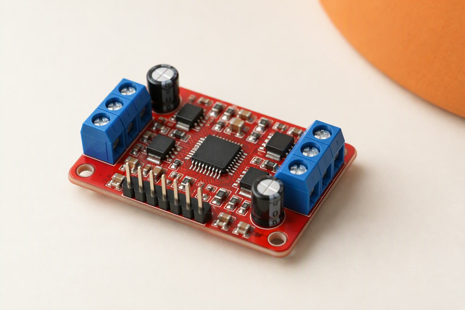
The TB6612FNG is a ₹180–₹400 dual H-bridge module that drops roughly 0.5 V instead of the L298N’s 1.4–2 V, accepts 3.3 V logic, and delivers an honest 1.2 A per channel — the real ceiling for a small robot car. It is the driver to reach for when the board is an ESP32, or when a 6 V pack needs to arrive at the motors as something close to 6 V. Treat the 1.2 A figure as the design limit, not the 3.2 A peak on the listing.
Key specifications
| Motor supply (VM) | 2.5–13.5 V |
|---|---|
| Logic supply (VCC) | 2.7–5.5 V |
| Channels | 2 H-bridges |
| Continuous current | 1.2 A per channel |
| Peak current | 3.2 A single pulse |
| Voltage drop | about 0.4–0.6 V at 1 A |
| PWM frequency | up to 100 kHz |
| Logic level | 3.3 V and 5 V compatible |
| Control pins | AIN1, AIN2, PWMA, BIN1, BIN2, PWMB, STBY |
| Standby | STBY must be HIGH to run |
| Thermal shutdown | yes |
| Module size | about 20 × 15 mm |
Substitute: L298N when the motor supply is above 13.5 V, or a DRV8871 when one motor pulls more than 1.2 A.
Why small robots moved to it
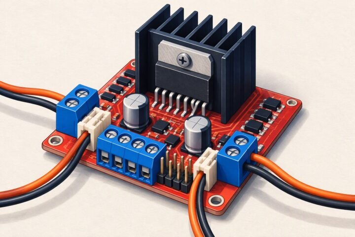
The chip contains two H-bridges built from MOSFETs, so it wastes far less energy as heat than the Darlington stages in an L298N. It needs no heatsink, mounts on a module smaller than a postage stamp, and switches fast enough for silent PWM. On a 7.4 V pack that difference is visible: the L298N leaves the motors around 5.6 V at load while the TB6612 leaves about 6.8 V, so the same motors spin faster on the same battery. The detailed comparison lives in L298N vs TB6612FNG.
Wiring, pin by pin
The header layout differs between modules, so read the silkscreen rather than copying a photo. The names are consistent:
- VM: motor supply, 2.5–13.5 V. This is the battery, not the 5 V rail.
- VCC: logic supply, 2.7–5.5 V. It must match the microcontroller: 5 V for an Uno, 3.3 V for an ESP32.
- GND: common for logic and motor supply. Join both grounds at the board, not through two thin jumpers.
- AO1 / AO2 and BO1 / BO2: the two motor outputs. To reverse a motor, swap its two leads rather than editing code.
- PWMA / PWMB: speed inputs. A duty cycle of 0–100% maps to 0–full speed.
- AIN1 / AIN2 and BIN1 / BIN2: direction inputs for each channel.
- STBY: standby. Pull it HIGH or the outputs stay off. Some modules tie it up; never assume yours does.
The control table
| IN1 | IN2 | PWM | Output |
|---|---|---|---|
| High | Low | High | Forward |
| Low | High | High | Reverse |
| Low | Low | High | Coast, outputs floating |
| High | High | High | Brake, outputs shorted |
| Any | Any | Low | Brake |
Coast and brake are different behaviours and the difference matters on a hill. Coast lets the robot roll; brake stops it. A line follower that overshoots corners usually wants brake, applied by pulling the PWM low rather than setting both direction pins low.
3.3 V logic is the real reason to buy it
The L298N expects 5 V logic levels, and driving it from a 3.3 V board is a gamble that works until it does not. The TB6612FNG specifies its logic supply from 2.7 V to 5.5 V, and its input-high threshold sits near 2 V, so a 3.3 V GPIO switches it cleanly when VCC is also 3.3 V. That is why ESP32 robot cars usually end up with this module.
Two rules keep it simple. First, power VCC from the same 3.3 V rail that feeds the microcontroller, not from 5 V, so the thresholds line up and no 5 V can reach a 3.3 V pin. Second, never power the module’s VCC from the motor battery; VM and VCC are separate pins for a reason. If you are moving from an Uno, the ESP32 DevKit V1 guide covers the 3.3 V pin limits you inherit.
Current, voltage drop and heat
The datasheet rating is 1.2 A continuous per channel with both channels running, and 3.2 A for a single short pulse. The output MOSFETs have an on-resistance of a few tenths of an ohm, which gives the 0.4–0.6 V drop at 1 A, and that drop becomes heat in a package with no heatsink. At 1.2 A per channel the board gets warm but stays usable; at 2 A it will reach thermal shutdown, which is a protection feature, not a normal operating point.
A pair of TT motors on a small chassis typically draws 300–800 mA together, comfortably inside the rating. The same pair stalled against a wall can pull 2–3 A, which is 1–1.5 A per channel — survivable briefly, not indefinitely. There is no current limiting and no current-sense output, so your code is the protection: detect a stall by watching for a wheel that should be moving, and cut the PWM. The power guide explains how to size the pack around that worst case.
Layout, noise and failure modes
Most TB6612FNG failures are wiring mistakes, not silicon failures. The chip has no reverse-polarity protection: connect VM backwards once and it is finished. Beyond that:
- Add 100–470 µF across VM and GND close to the board. Motor brushes generate spikes that the capacitor absorbs.
- Keep motor leads short and away from signal wires, especially encoder or I2C lines.
- Raise the PWM frequency if the motors whine. The Arduino default of roughly 490 Hz to 1 kHz is audible; the chip handles up to 100 kHz, so 20 kHz removes the noise on pins that support it.
- Do not hot-plug motors. Disconnect the battery before changing motor wiring; a loose motor lead under power can take the bridge out.
Because there are no big capacitors on most modules, a long battery lead is worth shortening before you blame the driver for resets. Two TT motors and a 7.4 V pack is the usual pairing, and it stays inside the ratings as long as the wheels are not jammed.
Common questions
Why does the motor not turn at all?
Check STBY first — it must be HIGH. Then check that VCC has logic power and that the grounds are joined. A module with only VM connected does nothing.
Can it replace an L298N in an existing robot?
Usually yes, if the motors draw under about 1.2 A each. It uses one more pin because of STBY, and the motor supply range tops out at 13.5 V.
Can it drive a single motor at 2 A?
No. Two channels of 1.2 A does not mean one channel of 2.4 A. For higher current, use a DRV8871 or a BTS7960.
Why do the motors buzz at low speed?
The default Arduino PWM frequency is in the audible range. Raise it to about 20 kHz on a pin that supports it, or accept the noise.
Related: L298N motor driver, line follower build, servo vs DC motor vs stepper.
Sources and further reading
- Texas Instruments L298 datasheet — the source for the 1.4–2 V Darlington drop this module avoids.
- Arduino language reference —
analogWrite()and PWM behaviour on AVR pins. - Espressif ESP32 documentation — 3.3 V GPIO levels and the LEDC PWM peripheral.
Last reviewed: October 2026. Limits are from the Toshiba TB6612FNG datasheet; module markings and pin order vary between clones. Prices are Indian retail ranges.
The TB6612FNG suits small geared motors; the motor selection guide shows how to work out whether it is big enough.