A stepper motor’s headline number, holding torque, is the one figure it produces while standing still. The moment it starts moving, torque falls with speed, and that curve decides whether your robot works.
This guide explains the torque-speed curve, why a 3 V rated motor runs happily on 24 V, what resonance does to a machine that looks fine on the bench, and how to measure the curve for the motor you actually bought instead of trusting a marketplace listing.
Holding torque is not running torque
Holding torque is the torque required to move the shaft one full step away from its detent while the coils are energised and the motor is stationary. It is measured at zero speed, with both phases at rated current, and it is the number printed on every listing.
Running torque is always lower. As speed rises, the coil current cannot rise fast enough to reach its target before the next step arrives, so the magnetic force weakens. That is why a motor rated at 0.45 N·m might deliver only 0.15 N·m at 600 RPM, and why the same motor behaves very differently on 12 V and 24 V supplies.
| Term | Meaning | Where you see it |
|---|---|---|
| Holding torque | Torque to break the shaft out of position while energised and still | Every product listing |
| Detent torque | Residual torque from the magnets with coils off | Datasheet only, usually 5 to 10 percent |
| Pull-in torque | Torque the motor can start and follow without losing steps at a given speed | Datasheet curves |
| Pull-out torque | Torque the motor can carry once already running at that speed | Datasheet curves, higher than pull-in |
For a robot, the useful number is pull-out torque at your operating speed, with a margin. Sizing on holding torque is the most common reason a machine stalls under load while the motor feels strong by hand.
Why the supply voltage changes everything
A stepper coil is an inductor. Current cannot change instantly, and the rate it rises is set by the inductance and the voltage available. Higher voltage pushes current into the coil faster, so the motor can reach its rated current at higher step rates. This is the single biggest lever on top speed.
# rough rise time for a coil, ignoring resistance
# t = L * I / V
L = 0.003          # 3 mH per phase, typical NEMA 17
I = 1.5            # 1.5 A rated current
for V in (12, 24, 36, 48):
    t_ms = (L * I / V) * 1000
    print(V, "V ->", round(t_ms, 2), "ms to reach rated current")
# 12 V -> 0.38 ms   24 V -> 0.19 ms   48 V -> 0.09 ms
This is why stepper drivers are called chopper drives. They apply a high voltage to force current in quickly, then switch it on and off rapidly to hold the target current. The motor’s rated voltage is almost irrelevant when a current-controlled driver is used; what matters is the driver’s maximum supply voltage and the current setting.
Practical consequence: if your robot needs speed, raise the supply voltage within the driver’s rating before buying a bigger motor. A 24 V supply on the same motor often doubles usable speed compared with 12 V. The TMC2209 versus A4988 comparison covers driver voltage limits and noise differences.
Reading a torque-speed curve
A datasheet curve plots torque on the vertical axis against step rate or speed on the horizontal. It usually shows two or three lines for different supply voltages and current settings. Read it like this:
- Flat region at low speed. Torque is close to holding torque and roughly constant. This is where the motor is comfortable.
- Knee. The point where torque begins to fall steeply. Operating above the knee means you are fighting inductance.
- High-speed tail. Torque approaches zero. Beyond this, the motor stalls regardless of load.
- Voltage lines. A higher-voltage curve sits above and extends further right. Same motor, more usable range.
Design to operate at or below the knee with a margin of at least 30 to 50 percent on torque. If your required torque sits near the tail, no amount of microstepping will save it.
Resonance: the bench behaves differently from the machine
A stepper has a mechanical resonance, often somewhere between 100 and 300 full steps per second depending on the motor and the load. At that speed it can buzz, lose steps or stall with almost no load. The same motor runs perfectly at 80 and at 400 steps per second.
Symptoms include a loud growl at one particular speed, vibration that appears only in a certain range, and a machine that misses steps only during slow moves. Fixes, in order of effort:
- Avoid the resonant band in your motion profile, or accelerate through it quickly.
- Use microstepping, which changes the step rate at which resonance appears and smooths motion.
- Add mechanical damping: a flexible coupling, a belt, or a small amount of inertia.
- Use a driver with stealth chopping or spread-cycle options, which reduce current ripple.
Microstepping does not increase torque. It increases resolution and smoothness, and can reduce resonance. A common myth is that 1/16 microstepping multiplies torque by sixteen; it does the opposite at high speed, because each microstep receives a smaller current increment. The missing steps troubleshooting guide covers the diagnostic order when a machine starts losing position.
Measure the curve for your own motor
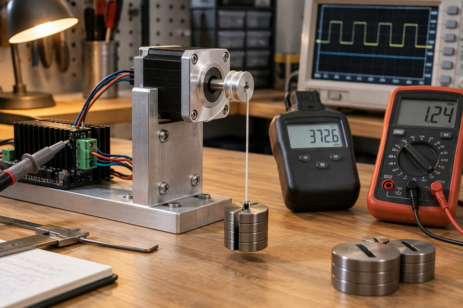
Marketplace listings are unreliable and datasheets are often for a different winding. A simple rig gives you a usable curve in an afternoon.
- Mount the motor firmly and fit a pulley of known radius.
- Hang a known mass from a string over the pulley. Torque is mass times gravity times radius.
- Command a constant speed and increase the mass until the motor loses steps.
- Record the speed and the last mass it carried reliably. Repeat at five or six speeds.
- Plot the points. The shape matters more than the absolute numbers.
# torque from a hanging mass
# T = m * g * r
m = 0.8        # kg that the motor just carried
r = 0.02       # pulley radius in metres, 20 mm
T = m * 9.81 * r
print(round(T, 3), "N.m")   # 0.157 N.m
Do this with the real driver, the real supply voltage and the real current setting. The curve you measure will be lower than the datasheet, and that measured curve is the one your machine will obey.
Sizing torque for a robot axis
Required torque is the sum of what the axis must overcome, multiplied by a safety factor. For a simple belt-driven linear axis:
# T_required = (F_total * r_pulley) / efficiency * safety
mass = 2.0            # kg carriage
mu   = 0.05           # linear guide friction
g    = 9.81
a    = 1.0            # m/s2 acceleration
r    = 0.02           # pulley radius
eff  = 0.9

F_friction = mu * mass * g          # 0.98 N
F_accel    = mass * a               # 2.0 N
F_total    = F_friction + F_accel   # 2.98 N
T = F_total * r / eff * 1.5         # 0.099 N.m with 50% margin
That number looks small, and it usually is at low speed. The problem appears when the same axis must move fast: at 0.1 N·m required, you need to find the speed where the motor still produces at least that much. If the curve crosses 0.1 N·m at 300 RPM, that is your practical speed limit, not the motor’s no-load maximum.
Gearboxes move the operating point. A 5:1 planetary reduction multiplies available output torque and divides speed, which often lets a small motor do a job that a direct drive cannot. The planetary versus spur gearbox comparison covers backlash and efficiency trade-offs.
Myths worth dropping
- “NEMA 17 means 17 N·m.” NEMA 17 is a mounting frame size, roughly 42 mm square. Torque depends on the winding and length, and varies widely within the same frame.
- “Higher current always means more torque.” Above the rated current you heat the motor and risk demagnetisation, and the driver may current-limit anyway.
- “Bigger motor is always safer.” More rotor inertia makes acceleration harder and can worsen resonance on a light axis.
- “Open loop is fine if the load never changes.” Loads do change, especially on robots that collide with things. Closed-loop steppers or servos exist for that reason.
Open loop, closed loop or servo
An open-loop stepper assumes the rotor followed every command. When it does not, the controller never finds out, and the machine quietly loses its zero. Closed-loop steppers add an encoder and correct position errors; servos close the loop with higher performance and higher cost.
| Choice | Cost | Behaviour | Use when |
|---|---|---|---|
| Open-loop stepper | Lowest | Silent position loss on overload | Light, predictable loads, 3D printers |
| Closed-loop stepper | Medium | Alarms on following error | CNC, heavier axes, unattended machines |
| AC servo | Highest | High torque at speed, precise control | Industrial axes, high cycle rates |
For a student robot arm, an open-loop stepper with a careful motion profile is usually enough, provided you home the axis at startup. For anything that runs unattended for hours, the cost of a closed-loop driver is small compared with a ruined part or a crashed tool.
If you are choosing between motor types rather than within steppers, motor selection for robots compares steppers with DC geared motors and servos, and NEMA 17 versus NEMA 23 covers the frame size decision. Wiring and basic code are in the stepper motor with Arduino guide.
Does microstepping increase torque?
No. It improves resolution and smoothness and can reduce resonance, but it does not add torque. At high step rates, very fine microstepping can slightly reduce usable torque because each microstep gets a smaller current increment.
Why does my stepper stall at high speed even with no load?
Inductance limits how fast coil current can rise. Above a certain step rate the current never reaches its target before the next step, so torque collapses. Raise the supply voltage within the driver rating or reduce the speed.
What supply voltage should I use for a NEMA 17?
Use the highest voltage your driver allows, typically 24 V for A4988-class drivers and up to 48 V for better ones, while setting current to the motor rating. The motor's low rated voltage assumes a simple non-chopper drive.
Why does the motor vibrate only at one speed?
That is mechanical resonance. Avoid the band, accelerate through it quickly, add damping, or change microstep settings to move the resonance to a less used speed.
How much torque margin should I design for?
At least 30 to 50 percent above the calculated requirement at the operating speed, using the torque at that speed rather than the holding torque.
Motor current at load feeds directly into the battery energy budget, so measure it before choosing a pack.
Sources and further reading
- Texas Instruments stepper driver overview — chopper drive theory and application notes.
- Analog Devices motion control — Trinamic stepper driver documentation.
- RepRap wiki stepper motor page — practical wiring, current and microstepping notes.
- Geckodrive support — stepper motor theory and torque curve explanations.