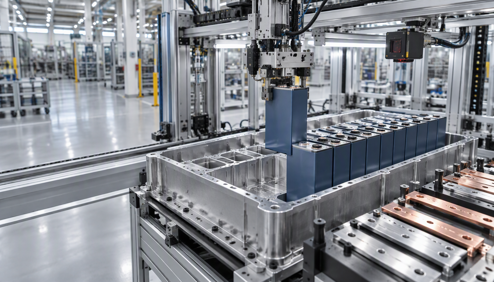
An EV battery pack line is five stages in sequence: cell grading, module build, tab and busbar joining, pack integration and end-of-line test. The joining and test stages decide whether the line earns its money, because they set both cycle time and scrap rate. Automate those first. Manual cell loading into a fixture is still economical at low volume, and very few Indian pack lines below a few thousand packs a year need a fully automated cell-handling line.
The five stages, and what decides quality in each
| Stage | What happens | Typical automation | What decides quality |
|---|---|---|---|
| Cell grading | Every cell is measured for capacity, internal resistance, open-circuit voltage and self-discharge, then binned so one module holds matched cells | Automated test rack with a sorter arm | Matching accuracy; a module is only as good as its weakest cell |
| Module build | Cells are stacked into the module frame with thermal interface material or structural adhesive, then compressed | Gantry or SCARA pick-and-place with adhesive dispensing | Stack-up tolerance and thermal contact |
| Tab and busbar joining | Cell tabs are joined to busbars and sense wires are attached | Laser, ultrasonic or resistance welding on a robot or gantry | Contact resistance, heat input and joint repeatability |
| Pack integration | Modules go into the enclosure with HV busbars, BMS harness, contactors and fuses, then the pack is sealed | Torque-controlled screwdriving, adhesive dispensing, vision-guided mating | Insulation, sealing and torque traceability |
| End-of-line test | Leak test, insulation resistance, cell voltage and temperature check, BMS communication, functional charge and discharge | Test bench with serial-number traceability | Whether a defective pack ever leaves the plant |
Only one of those five stages is genuinely difficult to engineer. Cell grading and module build are standard test-and-place work. Pack integration is torque and sealing discipline. The joining stage is where most of the process knowledge sits, and where most line failures originate.
Choosing the joining process
There is no single correct welding process for a battery pack, because a pack contains more than one kind of joint. A typical module has cell tabs to busbar, busbar to module terminal, and sense wires. Each has a different material stack and a different tolerance for heat.
| Process | Typical joint | Heat input | Access | Main risk | Best fit |
|---|---|---|---|---|---|
| Laser beam welding | Cell tab to busbar, aluminium or copper, similar or dissimilar | Very local and fast | Line of sight; clamping and fume extraction needed | Porosity, spatter, brittle intermetallics if energy is too high | High-volume prismatic and cylindrical modules |
| Ultrasonic welding | Multi-layer foil tabs to busbar | Solid state, no melting | Anvil required underneath | Tool wear; limited thickness per pass | Pouch cells and foil tab stacks |
| Resistance welding | Nickel strip to cylindrical cell can | Resistive heating at the joint | Electrodes on both sides | Electrode wear; stray current paths across the pack | Small cylindrical packs, low volume |
| Wire bonding | Thin aluminium wire to cell terminal | Low | Access to every terminal | Throughput; wire loop damage | Small packs and high-reliability niche builds |
| Bolted busbar | Busbar to module terminal | None | Tool access | Loosening and torque control | Serviceable packs and low volume |
Most production lines end up hybrid. Laser handles the high-count tab-to-busbar joints, ultrasonic handles foil stacks that a laser would burn through, and a bolted or laser-welded joint closes the module terminals. Specifying one process for the whole pack is usually a sign that the joint list was never written down.
Why aluminium to copper is the joint that catches people out
Aluminium and copper can be welded to each other, but the interface forms brittle intermetallic compounds. Too much energy grows a thick intermetallic layer, which cracks under thermal cycling. The joint still looks acceptable on the outside, while resistance climbs and the connection runs hot. This is the quiet failure mode of battery packs.
The controls are process-side, not inspection-side: keep heat input low, clamp the stack rigidly so contact is uniform, and choose a nickel-plated copper busbar or a bimetallic transition piece where the design allows one. Then verify with a cross-section and a resistance measurement. A shiny weld bead proves nothing.
The quality gates that separate a good line from a busy one
- Weld strength sampling. Destructive shear or pull tests per shift and per weld recipe, logged against the recipe, not just the part.
- Cross-section on first-off. Cut and polish after setup and after any recipe change to measure penetration and intermetallic thickness.
- Contact resistance or millivolt drop. The single most useful in-line check you can run, because it catches the joint that looks perfect and conducts badly.
- Leak test on the sealed pack. Air-decay or helium, depending on the enclosure specification. A leaking pack fails ingress protection before it ever reaches a vehicle.
- Insulation resistance and HiPot. Prove the HV isolation before the pack is energised for the first time.
- Serial-number traceability. Every weld recipe, torque value and test result tied to the pack serial. Without this, a recall becomes a whole batch instead of a date code.
Cycle time: count the joints before you buy the welder
Takt time is set at the joining station. Count the joints per module, multiply by weld time, add index and clamp time, then add handling. Once handling dominates, a second laser head or a split station beats a faster single head, because the bottleneck has moved from welding to moving. Vendors quote weld time; the line loses hours to clamping, fume extraction and re-fixturing, which are always priced separately.
What changes in India
AIS-156 is the Indian safety standard for the rechargeable energy storage system in road vehicles, and its later amendments add requirements around thermal propagation, battery management and ingress protection. Transport of lithium cells falls under UN 38.3 testing, cell-level safety under IEC 62133-2, and on-board pack safety under ISO 6469-1. Export programmes add IATF 16949 expectations and customer-specific weld and traceability rules.
The practical consequences land on the line design, not on the certificate: a cell-level fire detection and suppression strategy, fume extraction at every weld station, and test-data retention that starts before the first salable pack is built. Certification is a product exercise, but certification failure is almost always a process-control failure.
What to put in the integrator brief
- Cell format, dimensions and dimensional tolerance, including the tolerance you will actually accept.
- Module and pack CAD with the datum scheme the fixture will use.
- Joint list: joints per pack, joint type, material stack and coating.
- Required weld strength and contact resistance, and the exact method used to measure both.
- Takt time and shift pattern, so cycle time is quoted against a real demand.
- Scrap and rework policy, including whether a weld may be re-welded once or not at all.
- Traceability fields and retention period, agreed with your quality team and customer.
- Safety scope: cell fire risk, fume extraction, ESD and HV handling.
- Acceptance criteria for factory and site testing, written before the purchase order.
Common mistakes
- Buying the welder before designing the fixture. Joint quality is mostly clamping and contact.
- Quoting laser for a foil tab stack that ultrasonic welds better and cheaper.
- Relying on visual inspection instead of a 100% resistance check.
- Skipping serial traceability, then discovering it is needed on the day of a recall.
- Fully automating cell loading at a volume that does not justify it.
- Treating fume extraction and metal-fire risk as an afterthought in the cell layout.
Where to go next
If you are comparing pack assembly with the rest of a plant, read robotic assembly line design in India for tolerance and payback, and how to choose an industrial robot for the arm-versus-gantry decision. For the cell-side electronics, what a battery management system protects explains the sensing the pack line has to test. Line economics sit in industrial robot cost in India, and routine upkeep in the robot maintenance checklist.
For welding-adjacent process choice, robot spot welding covers guns and quality, and clinching versus self-pierce riveting versus spot welding covers the mechanical alternatives used on enclosures and trays.
Charging is the other half of the battery story; our guide to robotic EV charging in India covers depot charging, pantograph systems and what they cost.
Frequently asked questions
Do I need a fully automated line to build EV battery packs in India?
No. Most new lines start semi-automatic, with manual or semi-automatic cell loading, automated joining, and a 100% end-of-line test. Automation pays where the work is repetitive and quality-critical, which is joining, torque and testing, not necessarily handling.
Laser or ultrasonic for busbar welding?
Laser suits prismatic and cylindrical tab-to-busbar joints at high volume because it is fast and contactless. Ultrasonic suits multi-layer foil tabs where a melt defect is unacceptable. Many plants run both on the same line for different joints.
What is the most common quality escape on a pack line?
A joint that looks good and conducts badly. Visual inspection will not find it. Only contact-resistance or millivolt-drop measurement does, which is why an electrical check at the joining station matters more than a prettier weld.
How do I know the line will pass AIS-156?
AIS-156 is a product certification requirement, not a line requirement, but the line must repeatedly produce packs that pass it. That means leak, insulation and functional tests at end of line, documented traceability, and a thermal-propagation strategy designed into the pack. Agree the test plan with the certification body before the line is specified.
Can a battery pack joint be re-welded?
It depends on the design and the customer specification. Re-welding can raise local heat input and grow the intermetallic layer, so the permitted number of re-works must be fixed in the process specification and checked, not decided by the operator.
Sources and further reading
- Laserax: battery module busbar welding, lasers versus ultrasonic — process comparison for module interconnections.
- Choi et al., Micromachines 2025: tab-to-busbar interconnections in EV battery packs — review of resistance, laser and ultrasonic joining methods.
- Robotic assembly line in India — line design, tolerance and payback.
- Robot spot welding in India — welding guns and quality control.
- Industrial robot cost in India — what drives the number.