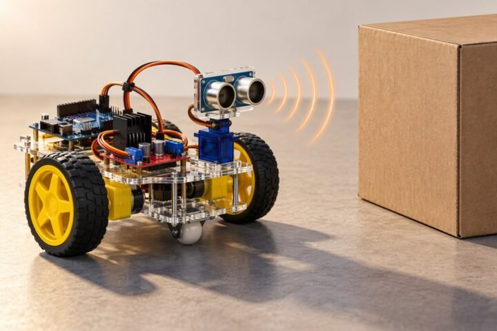
A ₹1,440 table-edge-safe robot that stops before it drives off. Two downward-facing TCRT5000 infrared sensors watch the surface under the front corners. When either one stops seeing the table, the robot stops, backs up and turns away. The page includes the pin map, a complete sketch without third-party libraries, a calibration routine, and a test plan built around the failures that make edge sensors unreliable.
Scope: beginner. This is a design worksheet with illustrative costs. It has not been bench-tested by this site, and the thresholds in the sketch are starting points you must calibrate on your own table. It protects against edges, not against obstacles; pair it with the obstacle avoiding robot if you want both.
How it behaves
Each TCRT5000 module has an infrared LED and a phototransistor facing the same way. Pointed at a light, matte table a short distance below the sensor, the module returns a strong reflection. At an edge the surface falls away and the reflection drops. The sketch reads both analog outputs about every 10 ms. If a reading moves far enough from the level measured on the table at start-up, the robot treats it as an edge: it stops, reverses for a short timed step, then turns away from the side that lost the table.
Stopping distance matters more than sensing. The sensors sit ahead of the wheels, so the robot has a few centimetres of margin. Keep the drive speed low enough that the robot can stop inside that margin; the test plan measures it.
Bill of materials
| Part | Qty | Unit | Total |
|---|---|---|---|
| Arduino Uno R3 | 1 | ₹520 | ₹520 |
| L298N motor driver | 1 | ₹180 | ₹180 |
| TCRT5000 reflective IR sensor module | 2 | ₹60 | ₹120 |
| TT gear motor with wheel | 2 | ₹110 | ₹220 |
| Acrylic chassis | 1 | ₹80 | ₹80 |
| 2×18650 holder with cells | 1 | ₹200 | ₹200 |
| Caster wheel and screws | 1 | ₹40 | ₹40 |
| Jumper wire set | 1 | ₹50 | ₹50 |
| Switch and foam tape | 1 | ₹30 | ₹30 |
| Parts total | ₹1,440 | ||
Scroll the table sideways to see every column.
Prices checked Nov 2026. Shipping and tools are not included.
Prices are illustrative figures for Indian sellers in November 2026, before shipping, and have not been checked against current listings. Use the cost calculator to compare sellers before ordering.
Pin map
| Module | Arduino Uno | Note |
|---|---|---|
| Left TCRT5000 AO | A0 | Analog reflection level, front-left, facing down |
| Right TCRT5000 AO | A1 | Analog reflection level, front-right, facing down |
| Sensor VCC / GND | 5V / GND | From the Uno 5V pin |
| L298N IN1 / IN2 | D5 / D6 | Left motor direction |
| L298N IN3 / IN4 | D12 / D13 | Right motor direction |
| L298N ENA / ENB | D3 / D11 | PWM speed. Remove the onboard jumpers. |
| L298N +5V | 5V pin | Powers the Uno from the driver’s regulator |
| All grounds | Common GND | Battery, L298N, Uno and both sensors |
Mounting the sensors
- Fix each sensor at a front corner, facing straight down. The working distance of a TCRT5000 is short, so check your seller’s notes and set the height by experiment.
- Place the sensors ahead of the wheel axis, as far forward as the chassis allows, to give stopping margin.
- Shield the sensors from direct sunlight and bright lamps if you can. Infrared from the sun or a halogen lamp raises the reading and can hide an edge.
- Do not mount a sensor where the caster wheel or a wire can pass under it.
The sketch
// Table-edge-safe robot: Uno + L298N + 2x TCRT5000 (analog)
// Design worksheet: calibrate EDGE_DROP on your own table before trusting it.

const int LEFT_SENSOR = A0;
const int RIGHT_SENSOR = A1;

const int IN1 = 5;
const int IN2 = 6;
const int IN3 = 12;
const int IN4 = 13;
const int ENA = 3;
const int ENB = 11;

const int SPEED = 120;          // keep low so the robot can stop in time
const int TURN_SPEED = 130;
const int EDGE_DROP = 150;      // change from the table level that counts as an edge

int leftTable = 0;              // reading on the table, measured at start-up
int rightTable = 0;

void setup() {
  pinMode(IN1, OUTPUT);
  pinMode(IN2, OUTPUT);
  pinMode(IN3, OUTPUT);
  pinMode(IN4, OUTPUT);
  pinMode(ENA, OUTPUT);
  pinMode(ENB, OUTPUT);
  Serial.begin(9600);
  stopMotors();

  // Calibration: place the robot flat on the table, then power it on.
  delay(2000);
  leftTable = average(LEFT_SENSOR);
  rightTable = average(RIGHT_SENSOR);
  Serial.print("table left=");
  Serial.print(leftTable);
  Serial.print(" right=");
  Serial.println(rightTable);
}

void loop() {
  int left = analogRead(LEFT_SENSOR);
  int right = analogRead(RIGHT_SENSOR);

  // Some modules give a higher analog value as reflection falls and
  // others a lower one. The absolute difference works for both.
  bool leftEdge = abs(left - leftTable) > EDGE_DROP;
  bool rightEdge = abs(right - rightTable) > EDGE_DROP;

  if (leftEdge || rightEdge) {
    stopMotors();
    delay(100);
    backward();
    delay(350);
    stopMotors();
    delay(100);
    if (rightEdge && !leftEdge) {
      turnLeft();
    } else {
      turnRight();
    }
    delay(450);
    stopMotors();
    delay(100);
  } else {
    forward();
  }
  delay(10);
}

int average(int pin) {
  long sum = 0;
  for (int i = 0; i < 16; i++) {
    sum += analogRead(pin);
    delay(5);
  }
  return sum / 16;
}

void forward() {
  digitalWrite(IN1, HIGH);
  digitalWrite(IN2, LOW);
  digitalWrite(IN3, HIGH);
  digitalWrite(IN4, LOW);
  analogWrite(ENA, SPEED);
  analogWrite(ENB, SPEED);
}

void backward() {
  digitalWrite(IN1, LOW);
  digitalWrite(IN2, HIGH);
  digitalWrite(IN3, LOW);
  digitalWrite(IN4, HIGH);
  analogWrite(ENA, SPEED);
  analogWrite(ENB, SPEED);
}

void turnLeft() {
  digitalWrite(IN1, LOW);
  digitalWrite(IN2, HIGH);
  digitalWrite(IN3, HIGH);
  digitalWrite(IN4, LOW);
  analogWrite(ENA, TURN_SPEED);
  analogWrite(ENB, TURN_SPEED);
}

void turnRight() {
  digitalWrite(IN1, HIGH);
  digitalWrite(IN2, LOW);
  digitalWrite(IN3, LOW);
  digitalWrite(IN4, HIGH);
  analogWrite(ENA, TURN_SPEED);
  analogWrite(ENB, TURN_SPEED);
}

void stopMotors() {
  digitalWrite(IN1, LOW);
  digitalWrite(IN2, LOW);
  digitalWrite(IN3, LOW);
  digitalWrite(IN4, LOW);
  analogWrite(ENA, 0);
  analogWrite(ENB, 0);
}
The sketch measures the table level once at start-up and compares each reading with it, so it adapts to a lighter or darker table. The start-up calibration assumes both sensors are over the table when you switch on; if one is over the edge, the baseline is wrong and the robot will misbehave. Whether a right-side edge should turn left depends on your motor wiring, so check the turn directions with the wheels lifted first.
Calibration, before the first run
- Open the Serial Monitor at 9600 baud and note the table readings printed at start-up.
- With the wheels lifted, hold the robot so one sensor hangs over an edge, and watch how far its reading moves with a short test sketch that prints
analogReadvalues. - Set
EDGE_DROPto about half of that change, so ordinary table texture does not trigger it but a real edge does. - Repeat with a dark placemat, a glossy surface and a glass top. Record which ones the sensor cannot read.
Test plan
- Sensors on the bench: print both readings and move a card under each sensor at several heights. Confirm the reading changes enough to set a threshold.
- Motor direction: confirm forward, backward and both turns with the wheels off the ground. Swap motor leads, not code, if a side is reversed.
- Stopping distance: put the robot on a low, safe table over a soft surface such as a folded towel on the floor. Drive it at the edge and measure how far past the sensor line the front wheels travel. If the wheels reach the edge, lower
SPEEDor move the sensors forward. - Angled approach: approach the edge at 45 degrees. One sensor should trigger first and the robot should turn away.
- Corner of a table: drive into a corner where both sides drop away. Record whether the robot escapes or oscillates.
- Surface changes: try a dark mat, tape and a printed page. Each can look like an edge or hide one; record which.
- Light: repeat near a window and under a lamp. A change in the table reading shows ambient infrared is leaking in.
What usually goes wrong
| Symptom | Likely cause | Fix |
|---|---|---|
| Reads the same over the table and over air | Sensor too high, or sunlight saturating it | Adjust the height by experiment, shade it |
| Stops on a patch of the table | Dark print, tape or a worn spot | Raise EDGE_DROP or keep the course uniform |
| Drives off a glass or black table | Surface does not reflect infrared | This sensor cannot see it; use a different method |
| Triggers randomly | Loose wire or motor noise on the analog line | Shorten wires, keep them away from the motors, average readings |
| Falls anyway at speed | Stopping distance longer than the sensor margin | Lower SPEED, move sensors forward |
| Edge missed at a corner | Only two sensors, both over the table | Add a third sensor at the centre or rear |
Upgrades
- More sensors: add a rear sensor so the robot does not back off an edge while reversing.
- Add an obstacle sensor: combine this with the ultrasonic scan from the obstacle avoider for a robot that avoids both walls and edges.
- Slow-down zone: use the analog value to slow the robot as the reading changes, before the hard stop.
- Time-of-flight sensor: a downward ToF sensor measures distance instead of reflection, so colour matters less; it has its own wiring and range limits to check first.
Cost and parts notes
The ₹1,440 total is an illustration for the parts above and does not include shipping. The L298N guide explains the voltage drop that makes a 7.4 V pack behave like a 5.8 V one at the motors, which affects how fast the robot really drives.
Common questions
Can it work on any table?
No. Infrared reflection depends on the surface. Light, matte tables work best. Glass, black or glossy surfaces may not return enough light, and this sensor cannot tell an edge from a dark patch.
Why use the analog output and not the digital one?
The digital output uses a threshold set by a small trimmer on the module. The analog value lets you calibrate in software and print readings, which makes faults easy to see.
Will it stop in time?
That depends on speed, sensor position and the surface. The sketch uses a low speed, but you must measure the stopping distance on your own robot, as the test plan describes.
Can I add an ultrasonic sensor too?
Yes. The pin map leaves D4, D8 and D9 free, so the obstacle avoider's sensor and servo pins can be added without a conflict.
Last reviewed: November 2026. This is a design worksheet with illustrative costs. It has not been bench-tested by this site; thresholds and timings are starting points, and measurements from your build are welcome.