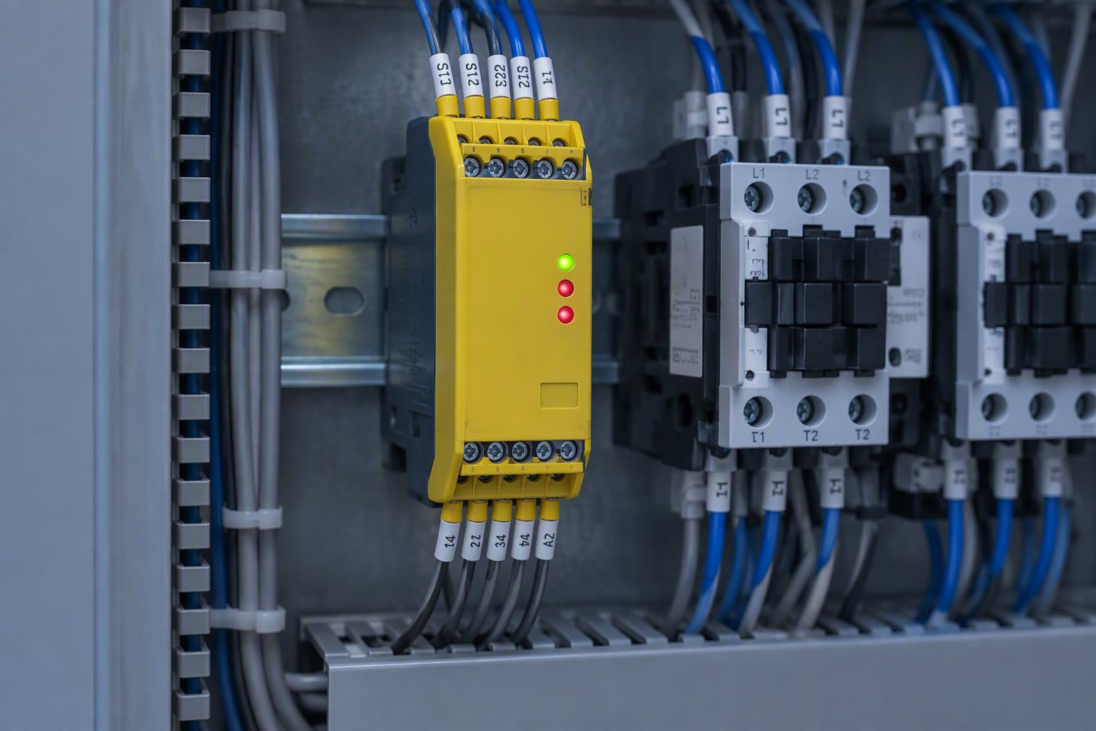
A safety function is only as good as the relay it lands on. A certified curtain wired into a standard relay is not a safety function.
This guide explains what a safety relay does, how to wire dual-channel inputs, the reset and feedback rules, the mistakes that leave a cell looking protected, and how to test the function properly.
What the relay is actually for
A safety relay monitors one or more safety inputs and removes power from hazardous actuators when any input opens. Its value is not the contacts; it is the monitoring. It detects a short between channels, a welded contact, a broken wire and sometimes a failure to open, and it refuses to restart until the fault is cleared.
| Device | Monitoring | Best for |
|---|---|---|
| Safety relay module | Dual channel, cross-fault, reset | One to three devices, simple cell |
| Safety controller | Multiple inputs, logic, zones | Several guards and interlocks |
| Safety PLC | Full logic and diagnostics | Large or changing cells |
| Standard relay | None | Not a safety device |
Dual channel and cross-monitoring
High-performance safety functions use two channels that must agree. If one channel opens, the relay drops out. If the two channels short together, the relay detects the cross-fault and refuses to start. That is why the two channels must be routed separately and not tied to a common terminal to save wire.
- Use separate terminals and separate cable cores for channel 1 and channel 2.
- Do not loop both channels through one contact block.
- Use test pulses from the relay where the input device supports them.
- Keep safety wiring in its own cable, away from motor cables.
- Label both channels at each end.
Typical cell wiring
A small cell might have an e-stop, a door switch and a light curtain feeding one safety relay, with the relay’s output contacts in the robot’s safety input and the drive enable circuit. The reset is a separate monitored input, not a button wired in parallel with the door.
E-stop       : dual channel, latching, mechanical
Door switch  : dual channel, positive opening
Light curtain: OSSD pair to safety inputs
Reset        : monitored push button, edge triggered
Feedback     : EDM contact from the contactors
Output       : two contactors, or robot safety input

Sequence: all inputs closed -> reset -> outputs energise
Any input opens -> outputs drop -> reset required
The exact terminals depend on the relay, but the logic does not: every protective device participates, and the restart is deliberate.
Reset rules
- Manual reset, from outside the guarded area, with a view of the hazard.
- Edge triggered: releasing the button must not restart the cell.
- Monitored: a stuck button or a shorted wire must be detected.
- Not automatic where a person can be inside the guard.
- Separate from the standard control reset, and labelled.
The EDM feedback contact
External device monitoring watches the contactors that the relay drives. If a contactor welds, the feedback contact stays closed and the relay refuses the next start. Without EDM, a welded contactor can leave the motor powered while the relay believes it has stopped the cell.
Wire the feedback contact in series with the reset or the monitoring input, as the relay manual specifies. It is one extra pair of wires and it closes a real failure mode.
Performance level in practice
ISO 13849 rates a safety function by its architecture, the reliability of its components, its diagnostic coverage and its resistance to common-cause failure. The relay’s own rating is only one term. A PL e relay fed by a single-channel switch is not a PL e function.
- Choose the architecture to match the required PL, not the other way round.
- Use devices with the diagnostic coverage the architecture assumes.
- Route channels separately to justify the claimed coverage.
- Keep proof-test intervals realistic for the plant.
- Document the calculation, not just the component certificates.
Choosing the relay
Start from the number of devices and the category you need, not from the price. A relay with too few inputs leads to series wiring that hides faults; one with too many adds cost and training burden.
- Count every protective device that must stop the same hazard.
- Check the input type: mechanical contacts, OSSD, or both.
- Check the output: relay contacts, semiconductor outputs, or both.
- Check the reset options: manual, monitored, edge triggered.
- Check the diagnostics: which fault does it report, and how?
- Check the housing: DIN rail width matters in a crowded panel.
- Buy one spare module, not a whole spare cell.
If the cell will grow, a small safety controller with configurable logic is often cheaper than replacing a relay later. The trade is software configuration that must be documented and tested, not just wires.
Testing that proves the function
| Test | Expected result |
|---|---|
| Open channel 1 only | Outputs drop, no restart until reset |
| Open channel 2 only | Outputs drop, fault indicated |
| Short channel 1 to channel 2 | Relay detects cross-fault, refuses start |
| Press reset while guard open | No start |
| Hold reset and close guard | No start if edge triggered correctly |
| Simulate welded contactor | EDM prevents restart |
| Remove power and restore | No automatic restart |
Record each test with the date, the tester and the result. A validation record with no measurements is a claim, not evidence.
Panel practice in Indian plants
- Keep safety circuits on their own terminals and colour-code the wiring.
- Do not mix 24 V safety wiring with 230 V control in one duct.
- Use ferrules and labels; a loose strand is a intermittent fault that defeats monitoring.
- Mount the relay where it can be seen and tested without dismantling the panel.
- Keep the manual and the wiring diagram inside the panel door.
- Lock the panel; unmonitored changes are how safety functions fail silently.
Mistakes that leave a gap
| Mistake | Consequence |
|---|---|
| Standard relay used for a safety input | No monitoring, no safety function |
| Both channels on one terminal | Cross-fault undetected |
| Reset wired in parallel with the guard | Guard bypassed by the reset button |
| Automatic reset with access | Restart with a person inside |
| No EDM | Welded contactor goes unnoticed |
| No test record | No evidence the function works |
| Safety wiring in the motor duct | Noise-induced nuisance trips |
A short commissioning order
- Check the wiring against the diagram before power is applied.
- Power up with the actuators isolated and confirm the relay’s fault indications.
- Test each input individually and in combination.
- Test the reset logic, including a held button and a stuck button.
- Test the EDM by simulating a welded contactor.
- Test the output at the robot and at the drive enable.
- Record every result and attach it to the handover file.
Related: robot safety standards in India, safety light curtains, safety laser scanners, PLC programming for beginners, integration checklist.
What does a safety relay do?
It monitors safety inputs such as e-stops, door switches and light curtains, detects faults including cross-channel shorts and welded contacts, and removes power from hazardous actuators until a deliberate reset.
Can I use a normal relay for a light curtain?
No. A standard relay has no monitoring and no fault detection, so the circuit is not a safety function regardless of the curtain's rating.
What is dual-channel wiring?
Two independent channels carrying the same safety signal, kept separate so the relay can detect a short between them or a failure on one. Tying both to one terminal defeats the monitoring.
What is EDM feedback?
External device monitoring: a contact from the driven contactors that confirms they actually opened. It prevents a restart after a contactor welds.
How often should a safety function be tested?
At commissioning, after any change, and at an interval set by the risk assessment and the proof-test requirements. Record each test with the date and result.
The cabinet that holds those relays needs the right ingress protection, as the IP rating guide explains.
Every interlocked gate depends on the safety circuit behind it, explained in the fencing procurement guide.
If the cell needs more than a few interlocked devices, check whether a safety PLC is the cheaper total, as our relay versus PLC comparison explains.