A vacuum gripper is a pressure calculation, not a suction cup catalogue entry. If the cup area and vacuum level cannot hold the part at the worst acceleration, no amount of clever mounting will fix it.
This guide covers the force calculation, cup selection, generator choice, air consumption, sensor and blow-off design, and the failure modes that appear only after a few thousand cycles.
The force equation
A vacuum cup holds a part because the pressure inside the cup is lower than atmospheric pressure. The holding force is the pressure difference multiplied by the effective area, minus a safety margin.
F = delta_P * A / safety_factor

delta_P = atmospheric pressure - pressure inside the cup
A       = effective suction area
At sea level, atmospheric pressure is about 101 kPa. A vacuum generator that reaches −60 kPa gives a pressure difference of 60 kPa. With a 30 mm diameter cup, the area is about 707 mm², or 0.000707 m².
F = 60,000 Pa * 0.000707 m2 = 42.4 N  (about 4.3 kg)

With a safety factor of 2:  usable load = 2.15 kg
With a safety factor of 3:  usable load = 1.43 kg
That last line is the important one. The theoretical force is not the working load. Use a safety factor of at least 2 for horizontal lifting with slow motion, and 3 to 4 for vertical lifting, high acceleration or a rough surface.
Safety factors by application
| Application | Minimum safety factor |
|---|---|
| Horizontal lift, smooth non-porous part, slow | 2 |
| Vertical lift | 3 |
| High acceleration or fast rotation | 3–4 |
| Porous or textured surface | 4 or more, with a flow check |
| Safety-critical handling above people | Redesign; vacuum alone is not enough |
The safety factor covers leakage, wear, surface contamination and the fact that a cup rarely seals over its full nominal area. A flat cup on a slightly curved part loses effective area at the rim, and the real force drops.
Choosing the cup
| Type | Best for | Limitations |
|---|---|---|
| Flat cup | Flat, rigid, smooth parts | Little compliance; poor on curved surfaces |
| Bellows cup | Curved, uneven or fragile parts | Less lateral stiffness; more height |
| Oval cup | Narrow parts such as strips and edges | Limited availability and higher cost |
| Foam cup | Textured or slightly porous surfaces | Wears faster; lower vacuum level |
| Metal cup | Hot parts and heavy duty | Hard sealing surface required |
Material matters as much as shape. Nitrile (NBR) is the general-purpose choice for oil-resistant industrial work. Silicone handles high temperatures and leaves fewer marks on glossy surfaces, but it tears more easily. Polyurethane resists abrasion.
Vacuum generators: ejector or pump
An ejector uses compressed air through a venturi to create vacuum. It is small, cheap, fast and needs no maintenance, but it consumes compressed air continuously while held on.
A vacuum pump is more efficient for high duty cycles and many cups, and it can maintain vacuum with less air consumption. It costs more, needs power and maintenance, and is noisier.
| Factor | Ejector | Pump |
|---|---|---|
| Response time | Fast | Depends on reservoir and line volume |
| Air consumption | Continuous while holding | Only through leakage |
| Number of cups | One per cup or small group | Many cups from one source |
| Maintenance | Very low | Filters, vanes, seals |
| Best for | Small, fast pick-and-place | High duty, porous parts, large areas |
Flow matters more than vacuum level on porous parts
Cardboard, cloth, foam and some plastics leak air through the material itself. A generator that reaches a deep vacuum on a sealed cup may never reach it on cardboard, because air keeps flowing through the part.
For porous parts, choose a high-flow generator and accept a lower vacuum level. A larger cup with a moderate vacuum can outperform a small cup with deep vacuum, because the limiting factor is the leak rate, not the pressure.
- Test with the real part, not a steel plate.
- Measure the vacuum level with a gauge while holding the part.
- Check whether the level holds or decays over ten seconds.
- Size the ejector from the measured leak rate, not from the catalogue headline.
Multiple cups and load distribution
Adding cups increases holding force but also increases leak paths and the risk that one cup not sealing drops the whole vacuum level. Options are to connect cups in parallel with a shared generator, or to give each cup its own ejector with a check valve.
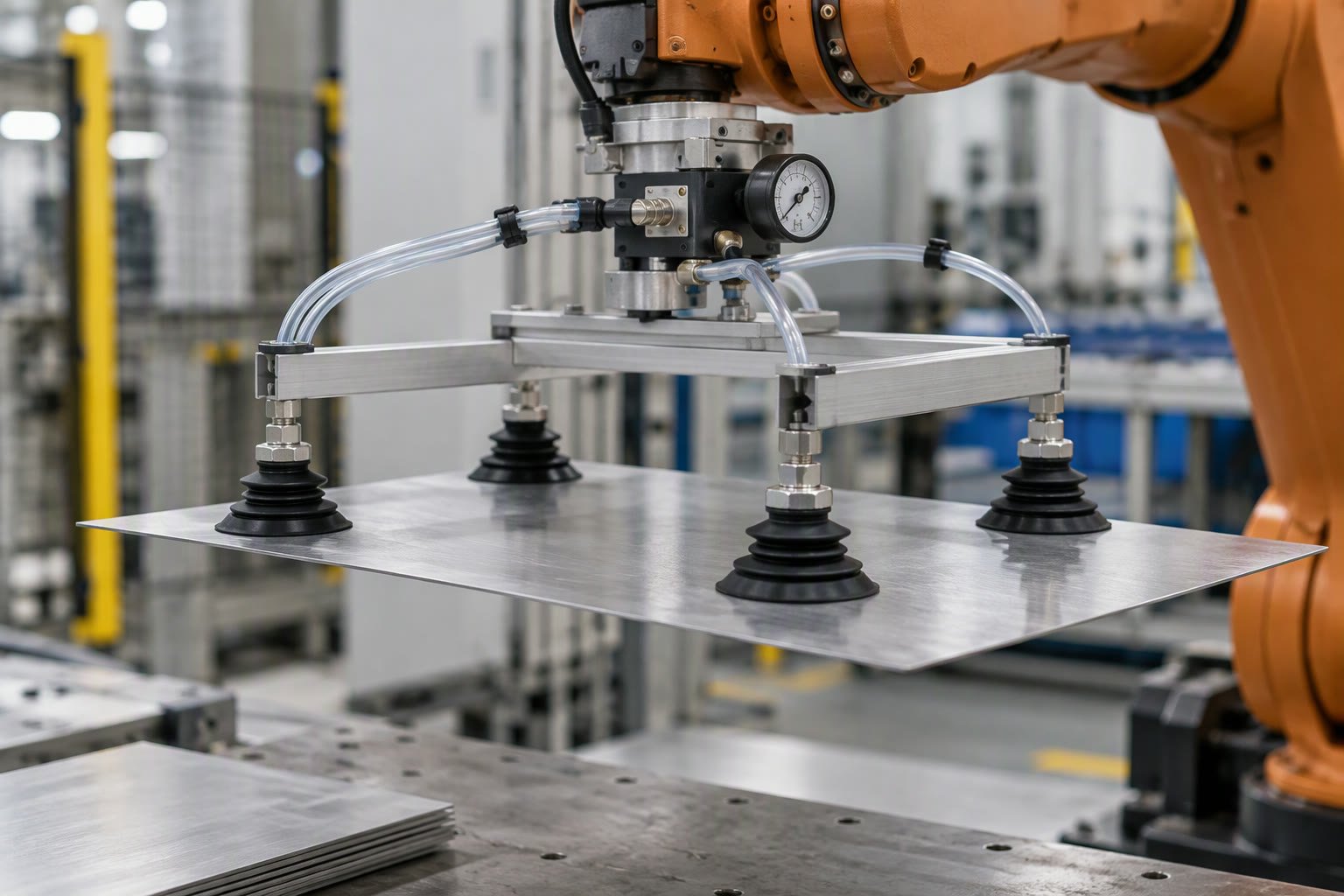
For a flat panel handled by four cups, parallel connection is fine if the panel is rigid. For a flexible part, individual circuits with a vacuum switch per cup let you detect a missed pick before moving.
Sensing and blow-off
Never assume a pick succeeded. A vacuum switch, also called a vacuum sender, confirms that the pressure reached a threshold within a time window. If it does not, the robot should abort the move rather than carry nothing and crash into the next station.
- Set the switch threshold below the normal holding level, not at it.
- Add a timeout for reaching vacuum; a slow pick usually means a bad seal.
- Use blow-off air to release parts that stick; many picks fail at release, not at grip.
- Filter the vacuum line; dust eventually blocks ejectors and switches.
- Log pick time and peak vacuum for predictive maintenance.
Lateral force and shear
A suction cup resists lateral force mostly through friction, which is much lower than its holding force. If the robot accelerates sideways while gripping, the part can slide even though the vacuum is fine.
Estimate the lateral capability as the holding force multiplied by the friction coefficient, which might be 0.3 to 0.6 for a smooth plastic on rubber. Then apply the same safety factor. This is why fast pick-and-place machines often add a mechanical stop or a gripper jaw alongside vacuum.
Failure modes after a few thousand cycles
| Failure | Cause | Fix |
|---|---|---|
| Cup tears at the rim | Wear, sharp part edges | Inspect on a schedule; use a rounded lip |
| Vacuum level drops slowly | Filter clogged, fitting loose | Service the filter, check push-fit fittings |
| Part slips sideways | Lateral acceleration too high | Slow the move or add a mechanical stop |
| Part sticks on release | Residual vacuum, oily surface | Add blow-off and a short dwell |
| Missed pick not detected | No vacuum switch | Add a switch with a timed threshold |
A quick sizing worked example
Part mass 1.2 kg, vertical lift, smooth plastic, four bellows cups of 25 mm diameter, ejector at −55 kPa.
Area per cup  = pi * (0.0125)^2 = 0.000491 m2
Force per cup = 55,000 * 0.000491 = 27.0 N
Four cups     = 108 N, about 11 kg
Safety factor 3 -> working load 3.7 kg
Part mass 1.2 kg -> margin is comfortable
Now check the lateral case. If the friction coefficient is 0.4, lateral capacity is about 43 N before the safety factor, or 14 N working. A 1.2 kg part accelerating at 8 m/s² needs about 9.6 N laterally, which leaves very little margin. Slow the move or add a stop.
Related: robot gripper buying guide, gripper design basics, end effector types, pick and place arm, machine vision lighting.
How much weight can a vacuum gripper lift?
It depends on cup area and vacuum level. A 30 mm cup at a 60 kPa pressure difference produces about 42 N, roughly 4.3 kg of theoretical force. With a safety factor of 3 the usable load is about 1.4 kg.
Why does my suction cup fail on cardboard?
Cardboard is porous, so air leaks through the material. The generator never reaches a deep vacuum. Use a high-flow generator, a larger cup, and accept a lower vacuum level.
Do I need a vacuum switch?
Yes on any automated pick. It confirms the pick succeeded and lets the robot abort before moving. Without it, a missed pick becomes a collision at the next station.
Ejector or vacuum pump?
Ejectors are cheap, fast and simple, but consume compressed air continuously. Pumps suit high duty cycles, many cups and porous parts, at higher cost and maintenance.
How do I stop parts sticking on release?
Add blow-off air and a short dwell before moving away. Residual vacuum and oily surfaces are the usual causes of a part that will not drop.
Vacuum cups need the same force budget as a pneumatic cylinder, worked through in cylinder and gripper sizing.
Wet and chilled food defeats many vacuum cups, and the food robot guide explains the alternatives.