A 12 V battery and a 5 V robot need a buck converter between them, and the ₹100 module most people buy is rated for a current it cannot hold. Choose the module by heat, not by the number printed on the listing. Choosing a buck converter for robots means sizing it by heat, not by the current printed on the listing.
What a buck converter does, and what it cannot do
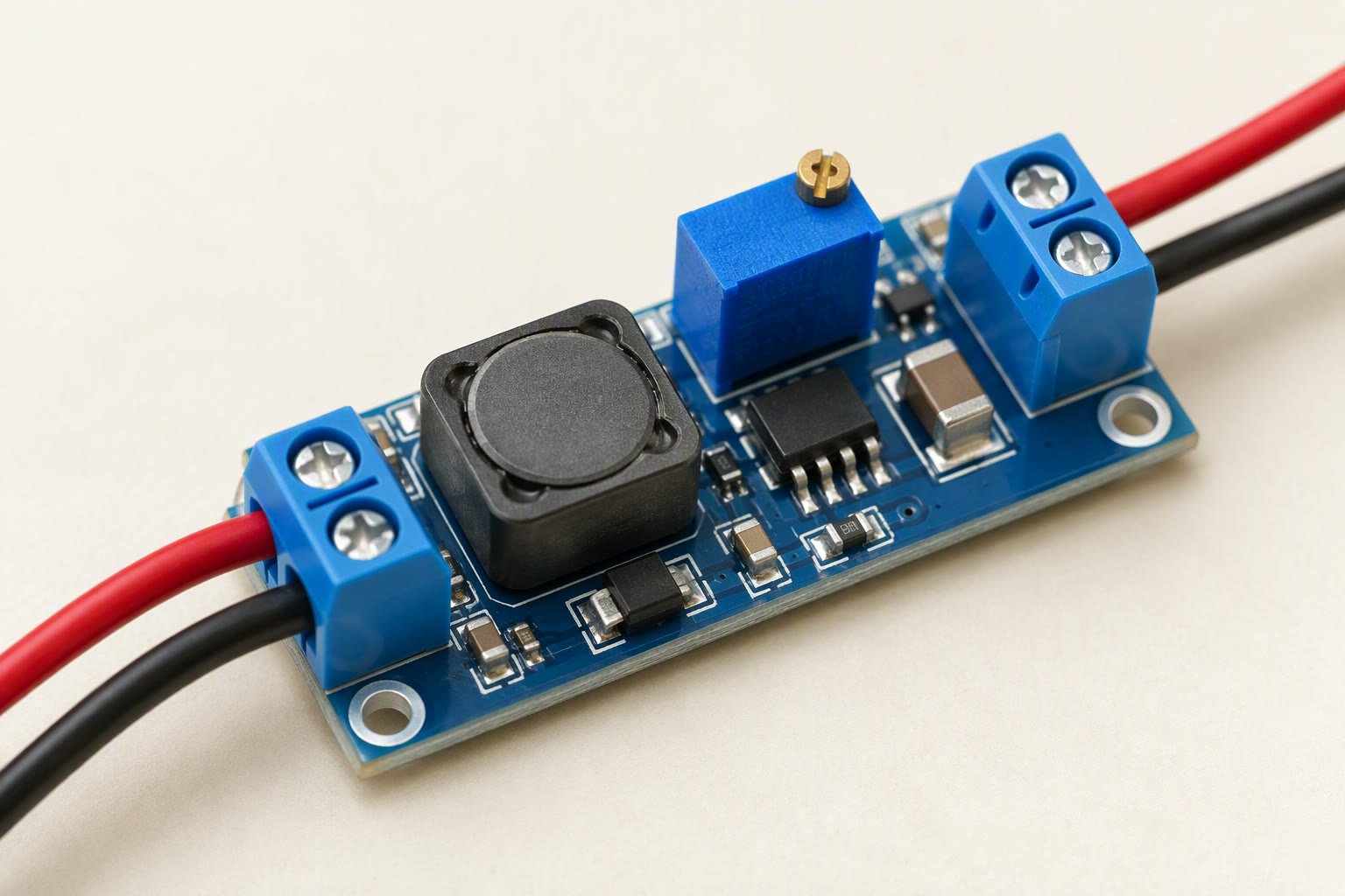
A buck converter switches the input on and off at high frequency and smooths the result through an inductor, so the output voltage is lower than the input with relatively little wasted power. A linear regulator such as a 7805 does the same job by burning the difference as heat: dropping 12 V to 5 V at 1 A turns 7 W into heat. A buck module at 85% efficiency loses about 0.9 W instead.
The catch is that a buck converter can only step voltage down. It also needs headroom: the input must stay roughly 1.5–2 V above the output. A 6 V pack cannot make a clean 5 V rail through a cheap buck module once the battery sags, and a 5 V USB bank cannot feed a 5 V buck at all.
| Module | Input | Output | Realistic continuous current | Typical price |
|---|---|---|---|---|
| LM2596 (red/blue board) | 4.5–35 V | 1.25–30 V adjustable | 1–1.5 A without a heatsink, 2 A with one | ₹80–₹150 |
| MP1584EN mini | 4.5–28 V | 0.8–20 V, fixed 5 V versions common | 1–1.5 A; the 3 A figure is peak | ₹60–₹120 |
| XL4015 | 8–36 V | 1.25–32 V adjustable | 3 A; 5 A only with a heatsink and airflow | ₹120–₹220 |
| 5 V 5 A synchronous module | 7–24 V | 5 V fixed | 4–5 A with a heatsink | ₹250–₹450 |
Those current figures are the honest ones. The LM2596 chip is rated at 3 A, but the module’s inductor, diode and copper area are not, and the chip limits current and drops out of regulation before it reaches that number. A module with no heatsink running at 2 A for a minute is hot enough to derate itself.
Size it by watts lost, not by the label
Heat is the whole design problem. Loss is roughly the output power multiplied by (1/efficiency − 1). At 12 V in, 5 V out and 80% efficiency, every amp of output costs about 1.25 W of heat inside the module.
| 5 V load | Output power | Heat at 80% efficiency | What that means |
|---|---|---|---|
| 0.5 A | 2.5 W | 0.6 W | Any module, barely warm |
| 1 A | 5 W | 1.25 W | LM2596 warm but usable |
| 2 A | 10 W | 2.5 W | Heatsink needed; MP1584 is out of its depth |
| 3 A | 15 W | 3.75 W | XL4015 or a synchronous module with airflow |
| 5 A | 25 W | 6.25 W | Not a ₹150 board; use a 5 V 5 A module or a UBEC |
A Raspberry Pi 4 wants 3 A at 5 V under load, which is 15 W and near the edge of an XL4015. A servo-heavy arm can pull 3–5 A in bursts. In both cases the buck module is the wrong place to save ₹200: a supply that browns out mid-move costs more in damaged SD cards and strange resets.
Set the output before you connect anything
- Power the module alone from the battery or a bench supply, with no load attached.
- Turn the trimpot until a multimeter reads 5.0–5.1 V. Adjustable modules ship at random settings, often near input voltage.
- Check under load. A module set to 5.0 V open-circuit may sit at 4.6 V at 2 A. If that happens, the module or the wiring is too small.
- Then connect the board. A Pi or ESP32 fed 20 V because the pot was never set is a dead board.
Wiring that survives motor noise
Motors are the reason robot 5 V rails misbehave. When a motor starts, stops or reverses it dumps current back into the supply, and the rail dips. Keep the motor current out of the logic path entirely: A buck converter for robots needs wiring that keeps motor noise off the logic supply.
- Battery → motor driver directly. Motors should not run through the buck converter.
- Battery → buck → logic and sensors. One converter for the board, a second for servos if the servo current is large.
- Input capacitor: 220–470 µF electrolytic across the buck input, close to the module.
- Output capacitor: 470–1000 µF across the 5 V rail near the load, plus a 100 nF ceramic.
- Short, thick leads: 18–20 AWG for the battery and motor runs. Voltage drop in long thin jumper wires looks exactly like a weak converter.
- Common ground between battery, converter, driver and board, joined at one point.
- A fuse on the battery positive, sized above the expected current. A shorted 2S pack can deliver far more current than any of these modules.
If the voltage measured at the board is lower than at the module output, the loss is in the wire or the connectors, not in the converter. Measure at both ends before replacing anything.
Buck converter for robots, UBEC or linear regulator?
| Option | Use it when | Avoid it when |
|---|---|---|
| Buck module | Input is well above 5 V and the load is steady | Load is above its real current rating, or the input is close to 5 V |
| 5 V UBEC | Servos or a Pi need 3–5 A and you want a sealed, heatsinked unit | You need an adjustable voltage |
| 7805 / AMS1117 | Small sensor loads under 300 mA on an Arduino | Anything above 500 mA, or a large input-to-output gap |
| USB power bank | Bench testing a board on its own | Motors, servos or anything that draws bursts |
The LM2596 component guide covers the module’s pinout and adjustment, and the robot power guide covers the whole supply budget including battery choice. If the robot runs from a 2S pack, read the battery guide first: 8.4 V fully charged is the number the converter has to survive.
Common questions
Can I use an LM2596 to power a Raspberry Pi 4?
Not reliably. A Pi 4 can draw 3 A at 5 V, which is more than an LM2596 module can hold continuously. Use an XL4015 with a heatsink, a 5 V 5 A module, or a proper 5 V 3 A supply.
Why does my 5 V rail drop when the motors start?
The motors are pulling current from the same source, or the wiring is too thin. Power the motors directly from the battery through the driver, keep the buck converter for logic, and add capacitors at the input and output.
Can a buck converter increase voltage?
No. It only steps down. For a higher voltage you need a boost converter or a buck-boost module, and those have their own current limits.
Why is the output 20 V when I power the module?
Adjustable modules ship at an arbitrary setting. Set the output with a multimeter before connecting any load, or the board will be destroyed.
Is a 3 A module safe for a 3 A load?
Not continuously without a heatsink. Treat the label as a peak figure and plan on half of it for anything that runs for minutes.
Related: LM2596 buck converter, 18650 battery pack, robot battery guide.
See also: the Pi 5 power rules for sizing a 5 V rail.
The pack side of the same design needs a battery management system.
A buck converter that is too small shows up as servo jitter under load and as brownout resets on the controller.
Module converters work on a bench, but a custom controller PCB removes the wiring failure points.
Sources and further reading
- Texas Instruments LM2596 datasheet — switch current limit, dropout and thermal behaviour.
- Buck converter — the switching principle behind efficiency and heat calculations.
Last reviewed: October 2026. Current and efficiency figures are typical published values for the module families named; individual boards vary. Prices are Indian retail ranges. Not bench-tested by this site.