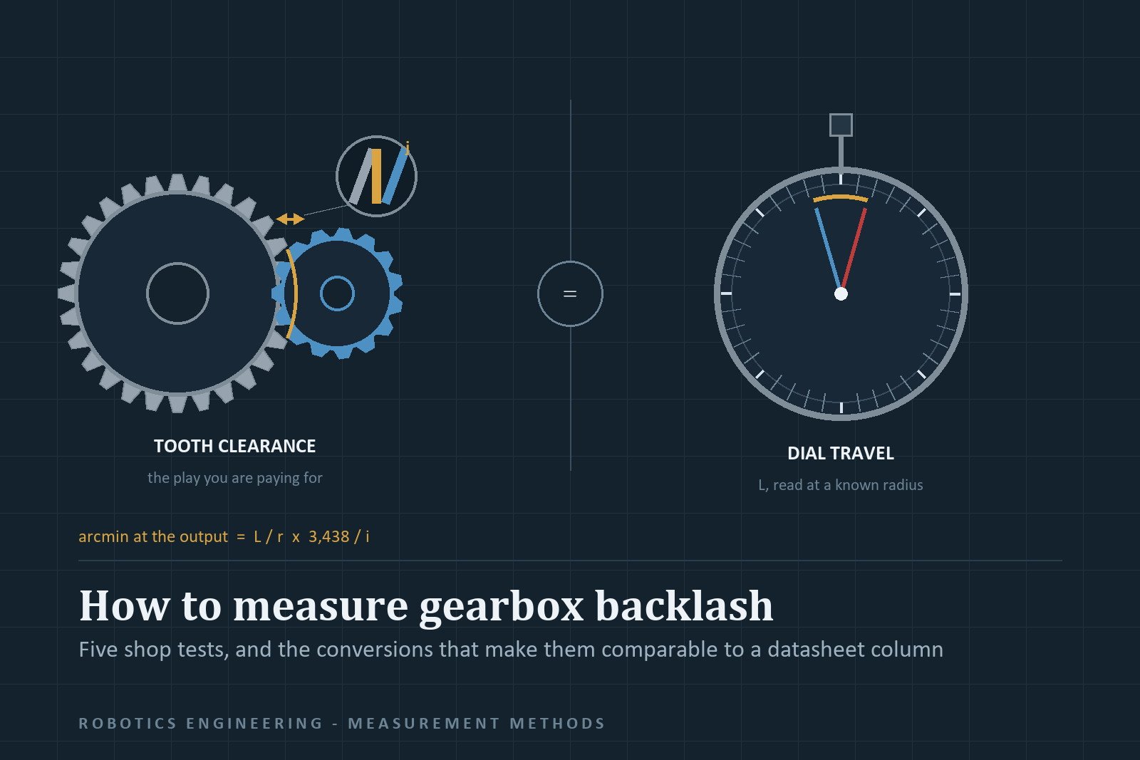
You measure gearbox backlash by blocking the output, rotating the input until the tooth flanks take up contact in each direction, and reading the travel between the two contact points with a dial indicator at a known radius. One identity carries every test on this page: play angle in radians = reading ÷ lever radius, and 3,438 arcminutes fit in one radian — so a 0.20 mm swing on a 20 mm drum over a 50:1 train is 0.20 ÷ 20 × 3,438 ÷ 50 = 0.69 arcminutes at the output. Everything else is deciding what your instrument is actually touching.
Flip point: a shop reading taken at an unstated load is not the datasheet’s backlash figure — it is clearance plus elastic wind-up at whatever force you used, comparable to nothing until you state or remove the wind-up term.
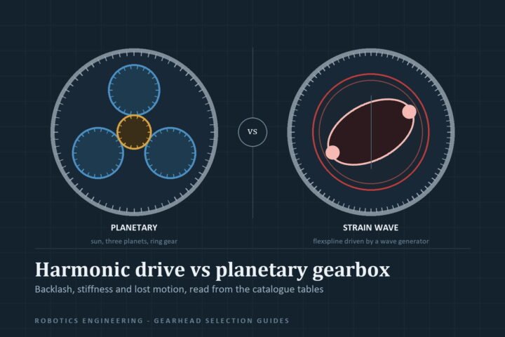
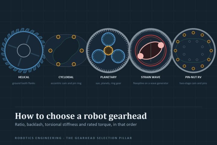
Three quantities share one word. Clearance is geometry: KHK defines backlash as “the excess thickness of tooth space over the thickness of the mating tooth” (KHK, PDF). Wind-up is deflection of those same teeth and shafts under your test force. System deadband is everything the gear does not see: couplings, bearings, a flexing arm. The five shop tests below separate them, cheapest first. Family choice is argued elsewhere — the harmonic drive versus planetary guide and the robot gearhead selection guide own the datasheet layer; this page is the ruler in your hand.
First, know which datasheet column you are testing
| Datasheet quantity | What was measured | Condition printed with it | Printed example |
|---|---|---|---|
| Circular backlash j (KHK) | Tooth-space excess over tooth thickness | Geometric, at the mesh, tied to a named shaft | jθ = 3440 × j ÷ pitch radius, arcmin (KHK, PDF) |
| “Backlash (typical)” | Flank play on reversal, output nearly unloaded | “measured at 2% of rated output torque and a single-stage transmission” (Apex page) | PII < 8~12; AB/AF/AD < 3~7; AH/AP < 1~2 arcmin |
| “Max. backlash jt” | Per-model ceiling, not an average | Sibling rows state conditions: no-load torque “at n1 = 3000 rpm and 20 °C gearbox temperature” (Wittenstein, PDF) | “max” and “typical” are different statistics |
| Hysteresis loss | Reversal width of the torque-versus-twist loop | “With the input locked, a torque is applied from 0 to ± Rated Torque” (CSF/CSG, PDF) | typical 3 arcmin, CSF sizes 8–32, ratio 30 (table 44) |
| Lost motion | Torsion in the low-torque band | “about ±4 % of the rated torque”, wave generator locked (HD Gears, PDF) | per size and ratio (table 1.1.9) |
| Positioning accuracy | Linearity error over one output revolution | “carried out without reversing direction” (CSF/CSG, PDF) | typical 2.0 arcmin, sizes 8–14, ratio 30 (table 40) |
| Repeatability | Spread returning to one position | “from the same direction”, half the maximum difference (HD Gears, PDF) | < ±0.1 arcmin (table 1.1.9) |
| Backlash/lost motion | One combined column per model | Per-model rows; the series bullet is looser | RV-6E row prints 1.5/1.5; the bullet claims “within 1 arc.min.” (Nabtesco, PDF) |
Read the condition column before the number column: Apex’s 2%-of-rated footnote is the rare honest one, and most pages print arcminutes and say nothing about force. That silence is why shop tests drift — KHK warns that machining errors make it necessary to “increase the amount of backlash by at least as much as the possible cumulative errors” (KHK, PDF).
Test 1 — clamp the output, rock the input, read a dial indicator
Cheapest, and the one that isolates the gear train. Lock the output flange against rotation (fixture, brake, or the arm braced against a stop), put a magnetic-base dial indicator on the input shaft or a drum of measured radius, rotate clockwise until the output side stops moving — flank contact — zero the indicator, rotate counter-clockwise until it reverses through full travel, and record the total reading L. That is backlash referred to the input shaft: the whole train’s play, shrunk by the ratio.
Convert in one line: L ÷ drum radius r, × 3,438, ÷ gear ratio i — worked above: 0.20 ÷ 20 × 3,438 ÷ 50 = 0.69 arcmin at the output. KHK makes the same instrument call at the mesh itself: feeler gauges are “impractical” for fine pitch, “whereas an indicator at the pitch line gives a direct measure” (KHK, PDF).
Two bounds. This is not one gear’s backlash: for a series of meshes “it is necessary to take into account the gear ratio of each mesh relative to a chosen reference shaft”, a linear play j becomes 3440 × j ÷ R arcminutes, and “an angular backlash must be specified with reference to a particular shaft” (KHK, PDF). This is not the whole joint either: an Oldham coupling adds play “outside the tooth engagement” that Harmonic Drive prints at 60 arcsec for a size-14 unit at ratio 30, falling to 5 arcsec on the larger frames at the higher ratios and gone with a solid wave generator (CSF/CSG table 45, PDF; HD Gears table 1.1.10, PDF). What the clamped-output test buys you is a bounded load case: with the output locked, the teeth carry only the friction torque of the input train, so the wind-up term is small rather than zero, and the stiffness rows in test 2 tell you how small.
Test 2 — back-drive with the motor unpowered
First pass needs no indicator: with the servo off, turn the output by hand and feel where the input does not yet move — Apex’s own observable, “minimal but measurable rotational backlash on the output side when the input side is stationary or just changes direction” (Apex page). To make it a measurement, stop or watch the input, bring the output to each side against the resistance, and read flange travel on an indicator at a measured radius.
Three errors to bound, all from published tables. Your hand is a torque transducer: Neugart prints the drag being felt — average idle torque from 0.05 Nm (PLE040) to 1.10–2.90 Nm (PLE160), ratio-specific via its Tec Data Finder (Neugart PLE, PDF) — and Harmonic Drive states its condition: no-load backdriving torque is “the torque required on the output side in order to backdrive the gear… no load gear input side, ambient temperature 20 °C” (HD Gears, PDF). Your push adds wind-up: 20 N on a 200 mm lever is 4 Nm, and Neugart’s torsional stiffness C2t of 0.7–1.0 Nm per arcmin twists a PLE040 by 4.0 to 5.7 arcmin before the clearance row (< 15 arcmin, single stage) is even counted; the same 4 Nm twists a PLE120 two-stage (17.5–22.0 Nm per arcmin) only 0.18 to 0.23 arcmin (PLE, PDF). On a small gearhead, most of what the hand feels is the test itself. Temperature moves the reading: running torque is printed “after 2 hours at 2000rpm input”, cold operation makes efficiency “low due to an increase in viscosity of the lubricant”, and “Standard temperature is the grease temperature during operation. It is not the ambient temperature.” (CSF/CSG, PDF) Record the grease temperature with the result.
Test 3 — static twist at the tool tip, and bounding the arm’s share
The one everyone actually does: indicator plunger on the tool flange, push the tip side-to-side against a stop or a spring scale, read the sweep. The pillar publishes the ruler this runs on — 1 arcmin = 2.91 × 10⁻⁴ rad = 0.145 mm at a 0.5 m tool radius (robot gearhead selection guide) — and extending it is one division: at 500 mm, a 0.10 mm sweep is 0.10 ÷ 0.145 = 0.69 arcmin.
The trap: the sweep is joint clearance plus gear wind-up plus link bending plus bearing play, reported as one number. Separate them with two loads: X1 at push torque T1, X2 at a different torque T2 (double the force is the easy recipe). Wind-up scales with torque; clearance does not. Worked at 500 mm: sweeps of 0.30 mm at 5 Nm and 0.56 mm at 10 Nm are 0.30 ÷ 0.145 = 2.07 and 0.56 ÷ 0.145 = 3.86 arcmin; the difference — 1.79 arcmin per added 5 Nm — is wind-up alone; the zero-torque intercept, 2.07 − 1.79 = 0.28 arcmin, is the deadband estimate; and 5 ÷ 1.79 = 2.8 Nm per arcmin is the effective joint stiffness, weaker than any catalogue gear row because the arm is in series with it. Check the gear’s share before blaming the reducer: Harmonic Drive computes twist θ = T/K1 below its first breakpoint and prints K1 = 2.4 × 10⁴ Nm/rad for a CSF-32 at ratio 30, listing the 29 Nm breakpoint at 4.3 arcmin (its own 12.1 × 10⁻⁴ rad column gives 4.2 at 3,437.75 arcmin per radian; the catalogue rounds slightly) (CSF/CSG tables 40–41, PDF). The 4 Nm hand push above is therefore 4 ÷ 24,000 = 1.7 × 10⁻⁴ rad = 0.57 arcmin of gear wind-up on that frame; on an RV-80E, whose “spring constant (reference value)” row reads 196 Nm per arcmin at 784 N·m rated torque, the same 4 Nm is 0.02 arcmin (Nabtesco, PDF). If the tip reading exceeds torque ÷ published stiffness plus the intercept, the rest is structure: the payload calculation guide works through the joint torque applied, and the repeatability versus accuracy guide sorts each layer into the ISO 9283 repeatability and accuracy terms a purchase spec uses.
Test 4 — read the drive: a reversal trace, not a single number
A powered joint reports its own deadband. In position mode, command small reversals around one target — a few times the expected play, at low speed, loaded as the application runs — and log position-command-minus-actual (the drive’s following error) against motor angle. Backlash leaves a flat signature: the motor moves, the load does not, the error grows, then snaps through the play at reversal. Repeat at several torques and the family of curves is the hysteresis loop — the object Harmonic Drive measures “with the input locked, a torque applied from 0 to ± Rated Torque” and reports as displacement B-B’ (CSF/CSG, PDF; HD Gears, PDF). The zero-torque intercept is the clearance column; the width at full torque is clearance plus wind-up, and only the second predicts where the tool actually lands.
Two honesty checks. “1 arcmin” from a planetary page — flank play at 2% of rated torque, single stage (Apex page) — and “1 arcmin” from a strain-wave page — loop width at up to full rated torque with the input locked — are different experiments. And the statistics differ: Wittenstein prints “Max. backlash jt”, a per-model ceiling, where Apex prints “typical” (Wittenstein, PDF). Compare a shop reading only against the column taken under its own condition, or the comparison is noise. If the symptom is overshoot or ringing at every reversal rather than a number, work the servo jitter and hunting guide and the servo drive selection guide first; backlash compensation in a drive assumes a repeatable deadband, and a trace is only repeatable if taken the same way.
Test 5 — what changes when the joint has a second encoder on the output
With feedback on the output shaft, the measurement runs itself. Omron’s C6-series manual states the arrangement: full closed-loop control “performs position control by using the second encoder installed externally to directly detect and feed back the mechanical position of the controlled object”, keeping the control “immune to position variations caused by mechanical errors or temperature” (Omron C6 manual, PDF). The number already exists inside the drive: the hybrid deviation is “the difference between the motor encoder feedback position and the second encoder feedback position”, with a default clear interval of 10 motor revolutions and a default excess-fault threshold of 100,000 pulses. Park the axis, command tiny reversals, and the hybrid deviation’s dead-to-live jump at each reversal is a live deadband measurement — through the real couplings, at the real temperature. Omron applies it in position and homing modes, “but cannot be used for” velocity and torque modes: a joint that must feel force watches its output encoder without closing position through it. Its own tuning advice assumes exactly this check — “Check and minimize backlash and structural deformation of the transmission mechanism”.
Resolution favours the output side. Harmonic Drive tabulates FHA-C quad encoder resolution 500,000 / 1,000,000 / 1,600,000 pulses per output revolution at ratios 50 / 100 / 160, footnoted “(motor encoder resolution) x4 x (reduction ratio)” and marked “The figures in the table are those at the output shaft” (general catalogue, PDF). Do the division: 21,600 arcmin in a revolution ÷ 500,000 counts = 0.043 arcmin per count — one arcminute of play is a 23-count step at reversal. The motor-side encoder alone cannot separate a gear reversal from a wind-up at all, and the output encoder still cannot see play upstream of it — where the Oldham coupling’s 5–60 arcsec sits (CSF/CSG table 45, PDF). Mount the scale after the coupling, not before it.
Converting once: the ruler and the reference shaft
Four lines of arithmetic carry every number above. (1) 1 arcmin = (1/60)° = π/10800 rad = 2.91 × 10⁻⁴ rad — Apex prints the same figure, 0.000290888 rad, and multiplies it out to “almost 3 mm deviation at 10 meters distance” (Apex page). (2) Millimetres at a radius = radians × that radius: 0.145 mm at 0.5 m (the pillar’s ruler), 2.91 mm at 10 m. (3) One radian is 3,437.75 arcmin, because a full turn is 2π rad and 21,600 arcmin — hence the × 3,438 in every conversion; KHK’s constant of 3440 in jθ = 3440 × j ÷ R is the same identity rounded (KHK, PDF). (4) Input-side arcminutes look i times more optimistic than the output-side figures datasheets quote. One assembly warning from the gear theory itself: at a 20° pressure angle, opening the centre distance by a adds backlash j = a ÷ 1.374, so a housing machined 0.05 mm loose gains 0.036 mm at the pitch line — 3440 × 0.036 ÷ 30 = 4.1 arcmin on a 30 mm pitch radius, more than most premium reducer rows, created entirely by assembly (KHK, PDF). Deeper involute geometry continues on the publisher’s mechanical-engineering information site, EngiTech.
What to record so the next measurement means something
A backlash number without its conditions is folklore. Record, every time:
| Field | Why it moves the answer | Precedent for stating it |
|---|---|---|
| Model, serial, ratio, stages | Apex’s figures are single-stage — “With multiple stages or higher ratios, the backlash may increase slightly”; Neugart prints < 15 (PLE040, 1 stage) to < 22 arcmin per frame and stage | Apex page; Neugart PLE, PDF |
| Test torque or % of rated | The makers’ columns live at 2% (Apex typical), ±4% (HD lost motion) or ±100% (hysteresis) of rated torque | table above |
| Which shaft, at what radius, which instrument | KHK: angular backlash must be named to a shaft; a dial reads a length | KHK, PDF |
| Speed and reversal count | Positioning accuracy is one output revolution without reversal; repeatability is same-direction only — different questions | CSF/CSG, PDF; HD Gears, PDF |
| Lubricant state and grease temperature | Running torque is printed “after 2 hours at 2000rpm input”; oil systems specify a first change at 100 h, then roughly every 1000 h | CSF/CSG, PDF |
| Ambient temperature, cycles since new | Backdriving torque’s stated condition is 20 °C; life and play drift with cycles | HD Gears, PDF |
| Arm load state (braced, extended) | Wind-up scales with torque; the same joint reads differently extended | geometry of tests 3–4 |
The acceptance question nobody publishes for you
Here the honest answer is a gap: every fetched document states nominal or maximum values for new units, none a wear limit. KHK words it — “excessive backlash is objectionable, particularly if the drive is frequently reversing or if there is an overrunning load” — with no arcminute number (KHK, PDF); Apex heads its class rows “typical”, Wittenstein “max”, and Neugart’s 20,000 h service-life line is footnoted as an application-specific configuration, not a wear endpoint (Neugart PLE, PDF); Nabtesco’s per-model play column carries a spring constant marked “reference value” in the same table whose series bullet claims “within 1 arc.min.” while RV-6E’s own row prints 1.5/1.5 (Nabtesco RV catalogue, PDF). Nobody publishes “reject at N arcmin”. So build the band from your own machine: commission every axis with test 1 or test 5 under the recorded conditions, keep the baseline trace, and set the limit where task accuracy actually fails — one arcmin is 0.145 mm at half a metre, and only your process knows whether that is sloppy or tight. For an in-service or re-manufactured joint, demand before-and-after numbers at stated load, and ask the question every catalogue dodges: what wear limit, tested at what torque, at what grease temperature? This site is published by the automation agency Jaadu Digital; put those questions into the same RFQ that carries the part number. Which family starts tighter when new is a different decision, argued in the harmonic drive versus planetary guide and, for moment-capable base joints, the cycloidal comparison — measure first, then compare to the right column.
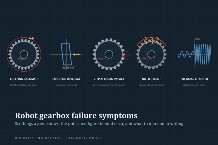
A reading that has moved over months is a different signal from one that was always high. Robot gearbox failure symptoms works through what creeping backlash, reversal-only error and a post-collision step change each point at, and which published limit applies.
Frequently asked questions
How do I measure gearbox backlash with a dial indicator?
Lock the output, touch the plunger on the input shaft or a drum of measured radius, rock the input to flank contact in both directions, and read the total travel L. Convert: arcminutes at the output = L ÷ drum radius × 3,438 ÷ gear ratio. L = 0.20 mm on a 20 mm drum over 50:1 is 0.69 arcmin. With the output locked the teeth carry only the input train's friction torque, so wind-up is small but not zero.
What is the difference between backlash, lost motion and hysteresis?
Backlash is tooth clearance, measured near zero load — Apex prints its class figures at 2 percent of rated output torque, single stage. Lost motion and hysteresis are reversal deflection under load: Harmonic Drive takes lost motion at about ±4 percent of rated torque with the wave generator locked, and hysteresis with the input locked and torque swept from 0 to ± rated. Compare your reading only against the column whose condition it matches.
Why is my measured backlash bigger than the datasheet says?
Three usual causes: you measured the whole train, not one mesh — play accumulates through stages, scaled to your reference shaft; your test force added wind-up the datasheet's low-load figure excludes — a 4 Nm hand push twists a PLE040 by 4-5.7 arcmin on published stiffness; or assembly added play — 20-degree gears run 0.05 mm over on centre distance gain about 4 arcmin per KHK's conversion.
How many arcminutes of backlash actually matter at the tool tip?
Convert before judging. One arcminute is 2.91 × 10^-4 radians: 0.145 mm at a 0.5 m tool radius, about 3 mm at 10 m. A 0.01 mm graduation at 0.5 m already resolves 0.069 arcmin, so instrument resolution is rarely the limit — which millimetre of process error you can pay for is.
Can a servo drive measure gearbox backlash for me?
Partly. Log position-command-minus-actual through small reversals at several torques and the widening loop is the hysteresis curve. With a second encoder on the output, drives like Omron's C6 compute the motor-encoder-to-second-encoder difference directly as a hybrid deviation — live lost-motion data. Velocity and torque modes cannot close position through the external encoder, and coupling play upstream of the gear still hides.
At what backlash value should a joint be rejected?
No maker document retrieved for this page publishes a wear limit; catalogues state nominal or maximum figures for new units with their own qualifiers. Set the limit from a commissioned baseline: repeat the same test under the recorded conditions, flag the drift your accuracy budget can no longer absorb, and hold any re-manufacturer to before-and-after numbers at stated load and temperature.