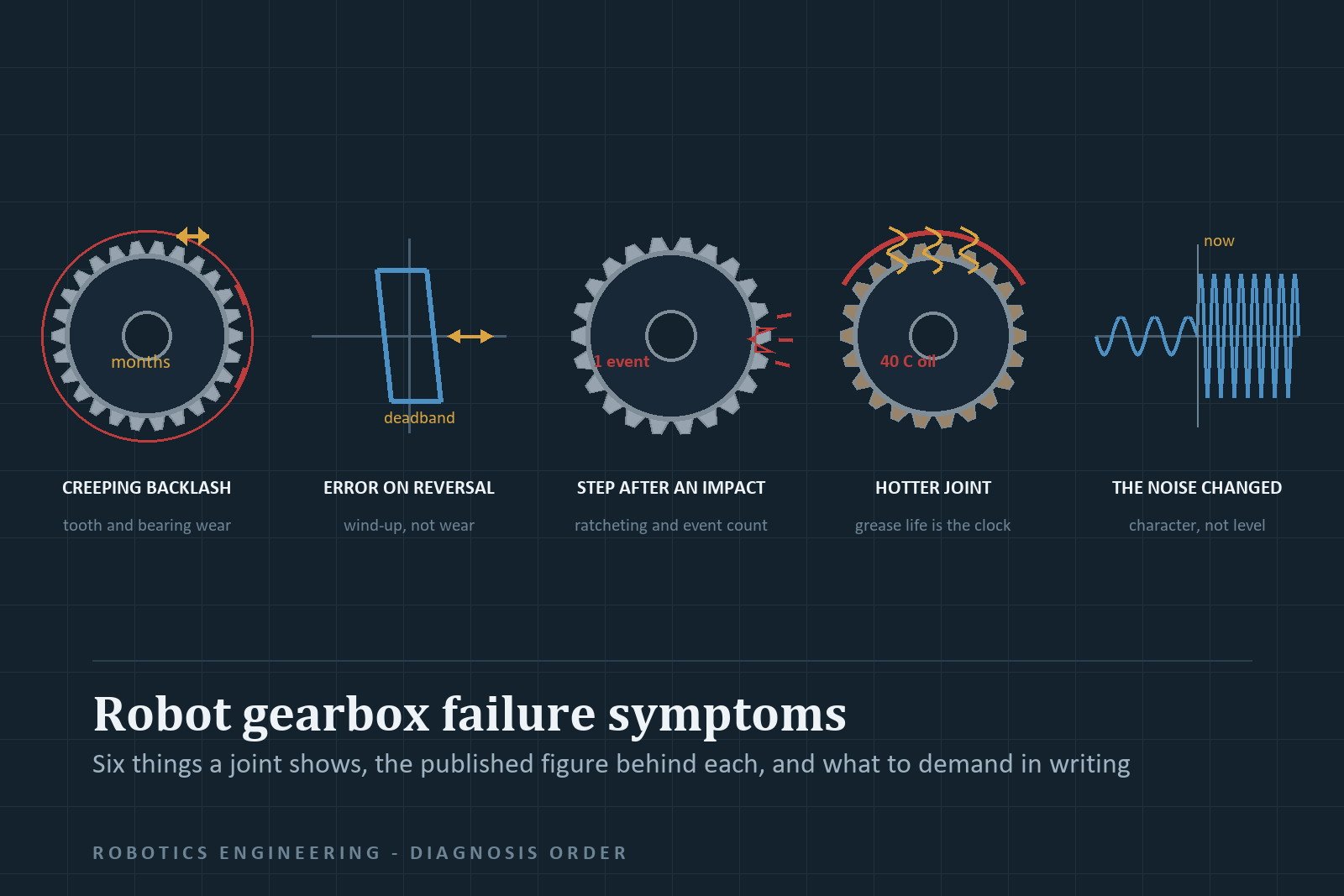
Six observable symptoms cover almost every gearbox failure in a robot joint: backlash that creeps up over months; a position error that appears only when the axis reverses; a step change after a collision or an emergency stop; noise or idle torque that has risen against its own baseline; a joint running hotter than it did when new; and a symptom that is not the gearbox at all. Each maps to a different mechanism, and each has a published threshold or measurement condition behind it. Nothing in these catalogues is unconditional: torque, speed, lubricant temperature, load direction, cycle count and mounting type all appear in the footnotes of the tables read as guarantees.
Flip point: if the change was sudden and coincided with an impact or an E-stop, stop trending numbers and start counting events. A strain wave gear’s remaining life is set by how many peak-torque occurrences it has already absorbed, and Harmonic Drive publishes that ceiling as an equation rather than as advice (CSF/CSG catalogue, PDF).
Symptom one: backlash that creeps up over months
A planetary gearbox loses accuracy in two ways and only one of them is teeth. KHK’s metric gear reference defines backlash as “the excess thickness of tooth space over the thickness of the mating tooth” and states both origins plainly: “tooth thickness is below the zero backlash value; and the operating center distance is greater than the zero backlash value” (KHK Elements of Metric Gear Technology, PDF). Flank wear is the first. Worn bearing seats, journals and housing bores are the second, and they push the centre distance apart: “any increase or decrease in center distance of two gears in any mesh will cause an increase or decrease in backlash” means a joint carrying side load gains free play with the gears barely touched. KHK calls excessive backlash “objectionable, particularly if the drive is frequently reversing or if there is an overrunning load”.
Two conditions hide it. First, temperature. KHK lists what rising temperature does: “Lower viscosity of lubricant. Accelerated degradation of lubricant. Deformation of housing, gears and shafts. Decreased backlash.” A warm machine can read tighter than the same machine cold, so trend a cold reading and a hot reading as a pair. A cold figure worse than the previous cold figure is the signal. Second is the condition behind each catalogue figure, which is not standardised between makers.
| Published figure | Maker and document | Condition printed with it |
|---|---|---|
| Planetary backlash, arc-min | Apex Dynamics backlash page | “measured at 2% of rated output torque and a single-stage transmission. With multiple stages or higher ratios, the backlash may increase slightly” (Apex backlash page) |
| Lost motion, arc-min | Harmonic Drive SE catalogue | “taken with an output torque of about +/-4 % of the rated torque” (SE Gears catalogue, PDF) |
| No-load starting, running and backdriving torque | Harmonic Drive SE and LLC | “ambient temperature 20 °C”, and the two LLC notes that the printed figures “indicate the maximum values” – starting torque “The lower values are approximately 1/2 to 1/3 of the maximum values”, backdriving torque “The typical values are approximately 1/2 to 1/3 of the maximum values” (CSF/CSG, PDF) |
| Mean no-load running torque | Wittenstein alpha CP/CPS | “(at n1 = 3000 rpm and 20 °C gearbox temperature)” (CP/CPS, PDF) |
| Positioning accuracy | Harmonic Drive LLC CSF/CSG | “The measurements are carried out without reversing direction” (CSF/CSG, PDF) |
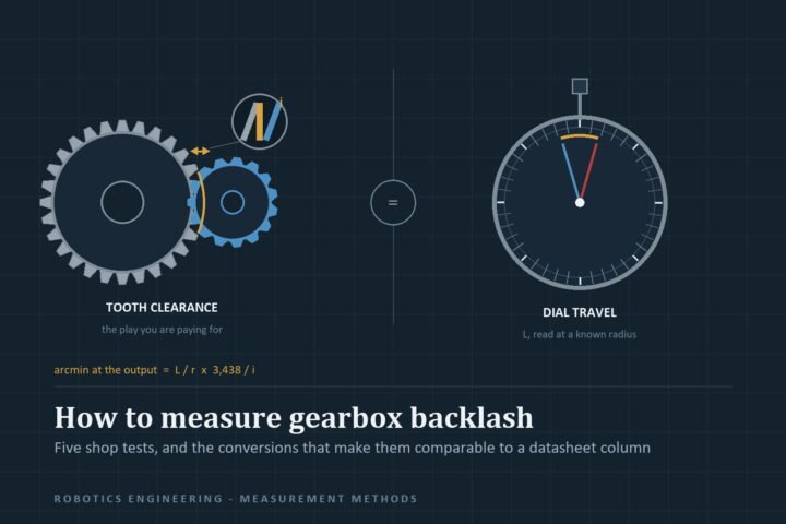
One maker’s arc-minute and another’s are therefore not the same measurement, and a dial-indicator reading at the output flange matches none of them unless you reproduce the load, speed and temperature. Trend your own baseline under fixed conditions; treat the datasheet figure as a class statement, not a warranty number.
Two quantities need no teardown. Neugart publishes both for the PLE line: an “Average idle torque” row from 0.05 N·m at PLE040 to 1.10-2.90 N·m at PLE160 single-stage, and a “Running noise” row of 58, 58, 60, 65 and 70 dB(A) across the five frames (Neugart PLE catalogue, revision 2026-05-08, PDF). Both are ratio-dependent, with per-ratio values sent to Neugart’s Tec Data Finder, so record your machine’s figures at commissioning. Idle torque rising at constant speed on a constant grease charge is mesh or bearing degradation; so is noise above its own baseline.
One bullet-versus-table correction, because Apex publishes both. Its features page claims the helical design gives “decreased backlash ( less than 1 arc-minutes and 56dB )”. The ABR table in the same catalogue carries three backlash classes – Micro P0, Reduced P1, Standard P2 – printed 4 to 9 arc-min across frames, with noise at 3,000 rpm no load reading 61 to 74 dB(A) (Apex AB/ABR catalogue, PDF). Quote the row, not the bullet.
Finally, check what the output shaft was carrying. Neugart’s PLE load rows give maximum radial force 200 to 5,000 N, axial 240 to 11,000 N and tilting moment 6 to 474 N·m; Apex footnotes its radial and axial rows “Applied to the output shaft center @ 100 rpm”, so a faster wrist sits outside the condition the figure assumes. Exceeding those rows does not fail the unit next cycle – it accelerates the centre-distance wear path, the mechanism to suspect when backlash grows on one axis of a six-axis arm and not the others. Over-greasing belongs on the same list: “too much grease can be harmful, particularly in an enclosed system. Excess grease will cause agitation, viscous drag and result in power loss” (KHK, PDF). A service action can manufacture the symptom it was meant to prevent.
Symptom two: the error appears only when the axis reverses
If repeatability in one approach direction is clean and the same angle approached from the other side lands elsewhere, the culprit is usually not wear.
Harmonic Drive publishes three accuracy numbers for one unit, measured three ways, which is why the same gearhead appears to have three different accuracies. Hysteresis loss is measured “With the input locked, a torque is applied from 0 to +/- Rated Torque”, and the CSF table prints 3 arc-min for sizes 8 to 32 at ratio 30, falling to 1 arc-min from size 14 at ratio 50. Positioning accuracy is measured over one output revolution “without reversing direction” – a test that structurally cannot see reversal error. In the FHA-C actuator table, one-way repeatability of +/-5, +/-5, +/-4 and +/-4 arc-seconds sits against bi-directional values printed 75, 30, 30, 60, 25, 25, 50, 20, 20, 50, 20 and 20 arc-seconds across four frames and three ratios (Harmonic Drive general catalogue, PDF). A bi-directional figure five to fifteen times worse than the one-way figure is the signature of reversal error, not of a worn tooth.
The second mechanism is elastic, and load dependence is how you separate it from backlash. Harmonic Drive states the torsional stiffness curve “is non-linear” and approximates it with three straight lines K1, K2 and K3; for CSF-32 at ratio 50 the printed breakpoints are T1 = 29 N·m at 1.9 arc-min and T2 = 108 N·m at 5.4 arc-min (CSF/CSG catalogue, PDF). The pillar works a real arm through: 153 N·m against the PLE120 two-stage band of 17.5-22.0 N·m per arc-min is 7.0 to 8.7 arc-min of wind-up, where the RV cell at 196 N·m per arc-min shows 0.78 arc-min (robot gearhead selection guide). Backlash is a constant deadband; wind-up grows with torque and vanishes at zero load. If the error tracks the commanded acceleration profile, you are looking at stiffness, not wear.
Zero-backlash marketing also carries a parts-list asterisk: “The gear element has zero backlash. However, an Oldham coupling is included as standard with all gearing components and gearheads … Unfortunately, the Oldham coupling does add a small amount of backlash to the system”, printed from 59 arc-seconds on a size-8 unit at ratio 30 down to the table minimum of 2 arc-seconds on sizes 90 and 100 at ratio 160 (6 arc-seconds is size 100 at ratio 50), with a “Direct Drive” option that removes the coupling (CSF/CSG catalogue, PDF).
The feedback side produces the same symptom from a different cause. Harmonic Drive gives actuator resolution as “(motor encoder resolution x 4) x (reduction ratio)” on a 2,500 counts per revolution motor encoder – a formula that only makes sense if counting happens before the gear train. Motor-side feedback cannot see anything downstream that slips, twists or loses steps: a belt, a coupling, a loose pulley, or the flexspline itself. Check that transmission before opening a gearbox. Two usual suspects on the drive side are on the servo jitter page and, for open-loop axes, stepper motor missing steps; the error-stack arithmetic is in the repeatability vs accuracy guide.
Symptom three: a step change after a collision or an emergency stop
This is the one symptom where the correct response is not a measurement.
Harmonic Drive defines the mechanism directly: “When excessive torque is applied while the gear is in motion, the teeth between the Circular Spline and Flexspline may not engage properly. This phenomenon is called ratcheting and the torque at which this occurs is called ratcheting torque. Ratcheting may cause the Flexspline to become non-concentric with the Circular Spline … Operating in this condition may result in shortened life and a Flexspline fatigue failure.” The consequence is self-amplifying: “Once ratcheting occurs, the teeth wear excessively and the ratcheting torque may be lowered.” The English-language SE catalogue names the resulting wrong-hand mesh “Dedoidal” and adds the check a workshop can run – uneven rotation by hand indicates that state (Harmonic Drive SE catalogue, PDF; CSF/CSG, PDF). Past the next limit, buckling, the SE glossary is blunt: “the Flexspline may experience plastic deformation, eventually leading to a rupture at the bottom of the Flexspline … When the Flexspline buckles, early failure of the Harmonic Drive Gear will occur.”
The limits are published as a ladder for one size and ratio. Here is the whole ladder for CSF-32 at ratio 50, transcribed from the rating, ratcheting and buckling tables of one document (CSF/CSG catalogue, PDF):
| Limit, CSF-32 ratio 50 | Printed value | Multiple of rated | What it governs |
|---|---|---|---|
| Rated torque | 76 N·m | 1.00x | continuous load at 2,000 rpm input |
| Limit for average torque | 108 N·m | 1.42x | duty-weighted load, not peaks |
| Limit for repeated peak torque | 216 N·m | 2.84x | acceleration and deceleration |
| Limit for momentary peak torque | 382 N·m | 5.03x | collision and E-stop, event-limited |
| Ratcheting torque | 980 N·m | 12.9x | teeth stop engaging in motion |
| Buckling torque | 2,200 N·m | 28.9x, all-ratio row | flexspline plastic deformation |
The definitions are load-path specific: rated torque “indicates allowable continuous load torque at 2000 rpm input speed”, repeated peak exists because “during acceleration a deceleration the Harmonic Drive gear experiences a peak torque as a result of the moment of inertia of the output load”, and momentary peak is the collision budget, which “should, under no circumstance, occur during normal operating cycle”. Note also that the two Harmonic Drive publishers do not put the top two rows in the same place: the SE glossary describes ratcheting as “excessive torque (8 to 9 times rated torque)” and buckling as “highly excessive torque (16 to 17 times rated torque)”, both with “The values … can be provided on demand by Harmonic Drive SE”, while the LLC per-model rows put ratcheting at 12.9x rated for this size and ratio and print an all-ratio buckling figure that maps to 28.9x. Use the per-model row where it exists and demand the number in writing where it does not; a multiplier band is not a design input.
The event ceiling is where the arithmetic matters. The maker prints “[Equation 7] N = 1.0 X 10^4 / (2 X n X t/60)”, where n is “Input speed before collision (r/min)” and t is “Time interval during collision (sec)”, with the note “If this number is exceeded, the Flexspline may experience a fatigue failure.” Its own selection example, 14 rpm output through ratio 120 over a 0.15 second collision, resolves to 1,190 events. Applying the printed equation to three more duty pairs gives 1,000 events at 3,000 rpm input and 0.10 s, 4,167 at 480 rpm and 0.15 s, and 595 at 1,680 rpm and 0.30 s – all derived here from Equation 7, not published as a set. The lever is input speed: the ceiling goes as 1 / (n x t), so the same impact costs a high-speed wrist about 3.5 times the events it costs a geared-down base joint. Count crash and E-stop events per joint; this is life you cannot inspect. Planetary makers express the same idea as cycle allowances – Neugart footnotes its emergency-stop row “(3) Permitted 1000 times”, Wittenstein permits its emergency stop “1000 times during the service life of the gearbox” with acceleration torque at “max. 1000 cycles per hour”, and Apex prints emergency-stop torque as “3 times of Nominal Output Torque”, acceleration capped at 60% of it (Neugart PLE, PDF; Wittenstein CP/CPS, PDF; Apex AB/ABR, PDF).
Oversizing buys life on a cube. Harmonic Drive’s law is “[Equation 8] Lh = Ln x (Tr/Tav)^3 x (Nr/Nav)” with “Nr : Rated input speed (2000 rpm)”, against L10 lives (L10 being the life reached with a 10 % probability of failure) of 7,000 hours for CSF and 10,000 for CSG. Doubling torque margin multiplies bearing life by eight, and the maker’s worked example lands at 7,610 hours for a unit running above rated torque. The same equation reads as a warning: at rated torque with the 3,500 rpm grease-lubricated average-input ceiling from the same table, it leaves 7,000 x 1 x (2000/3500) = 4,000 hours before any margin at all. Both the rated and the repeated peak figures “are based on an infinite fatigue life for the Flexspline” – the headline is a bearing-life number, and the flexspline decides whether you reach it. Nabtesco frames its equivalent honestly: rated life “Indicates the time (L10 life) until life is reached due to interior wear and component deterioration, when the reduction gear is continuously operated in one direction at rated torque and rated output speed”, printed as 6,000 hours from RV-6E to RV-450E and 9,000 for the RV-1500E, with a separate RF-P series at 20,000 hours (Nabtesco RV catalogue, PDF). One direction. A reciprocating joint is not that duty.
Symptom four: the joint runs hot and the grease is the reason
Heat is the common upstream cause of symptoms one, two and three, and lubricant is the cheapest lever. The three makers state genuinely different positions, so treat this as a specification question rather than a maintenance habit.
Neugart’s current PLE chapter lists both standard and food-grade lubrication as “Grease (lifetime lubrication)” alongside a stated service life of Lh = 20,000 hours (printed footnote (2): “Application specific configuration with NCP”), with Tmin -25 °C, Tmax 90 °C and IP54 (Neugart PLE, revision 2026-05-08, PDF). The conditional is inside the claim: the wider catalogue copy of the same family promises maintenance-free operation only over the service life and only “under normal operating conditions”, and this chapter’s own footnote hangs its 20,000-hour row on an application-specific configuration. The footnotes are the whole argument.
Harmonic Drive SE conditions the same claim: under what it calls regular operating conditions — average ambient temperature at or below 40 °C, average application load at or below rated torque or rated speed — “the initial lubrication … is sufficient for lifetime lubrication of the gear. However, in case of long term high lubricant temperatures, a high load on the gearbox or a long operating time, a grease change may become necessary.” Its diagram plots lubricant service life in wave-generator revolutions from 1E+7 to 1E+10 against lubricant temperature from 20 to 120 °C for four named greases, and the worked example is the useful part: a CSG-17-80-2UH on SK-2, 29 N·m rated against 35 N·m average at 300 rpm and 40 °C, reads LGTn = 8.5 x 10^8 revolutions, is corrected by the cube law to 4.83 x 10^8, and lands at 26,862 operating hours (Harmonic Drive SE catalogue, PDF). The LLC document carries the identical cube law as Equation 9 and one sentence that will save you a wrong conclusion: “Standard temperature is the grease temperature during operation. It is not the ambient temperature.” Your shop at 35 °C tells you nothing about the grease in a sealed joint (CSF/CSG catalogue, PDF). The LLC text also flags where grease dies first: “The grease has the highest deterioration rate in the region where the grease is subjected to the greatest shear (near wave generator).”
Nabtesco drops the lifetime framing altogether: “Standard lubricant replacement time is 20,000 hours. However, when using with reduction gear surface temperature at or above 40 °C, check the lubricant for deterioration or contamination and replace it sooner”, and “Use under operation conditions such that the reduction gear part surface temperature does not exceed 60 °C. Use exceeding this temperature may lead to damage.” Two more conditions belong in a diagnosis, both printed as notes: exceeding the allowable no-load output speed “may lead to heat generation and wear”, and “When the swivel angle range is small (within 10°), lubrication defects and internal part load are concentrated, potentially shortening the reduction gear rated life” – a pick-and-place joint that oscillates through a few degrees starves its own gearing. KHK gives the thermodynamics for the involute case: grease is “Not suitable for use under high load and continuous operation. The cooling effect of grease is not as good as lubricating oil”, and “New high-performance lubricants can withstand up to 80 to 90 °C. This temperature can be regarded as the limit” (KHK, PDF).
| Lubricant position | Maker and document date | Published interval or condition |
|---|---|---|
| Lifetime grease, maintenance-free under normal conditions | Neugart PLE chapter, revision 2026-05-08; complete catalogue 05/2025 | no interval published; Lh 20,000 h stated; IP54, Tmax 90 °C |
| Lifetime only if ambient at or below 40 °C and load at or below rated | Harmonic Drive SE catalogue, file dated 2026-05-28 | computed from a temperature diagram plus a cube law; worked example 26,862 h |
| First oil change after 100 operating hours, then every 1,000 | Harmonic Drive SE, oil-lubricated option | table states both intervals; magnetic drain plug lets the first change be omitted “please consult Harmonic Drive SE” |
| 20,000 h grease replacement, sooner above 40 °C surface | Nabtesco RV catalogue | hard ceiling at 60 °C surface temperature; non-designated lubricants void the warranty |
Three service facts that decide whether a symptom is yours or the supplier’s. Harmonic Drive SE publishes a running-in procedure – “Operate the gear for a period of about 20 minutes or longer without load or with a very low load”, at “ideally about 1000 rpm (but not higher than 3000 rpm at the maximum)”, keeping “the internal operating temperature below 80 °C”, and warns that “When using non-standard lubricants, the performance data of the gears cannot be guaranteed” (Harmonic Drive SE catalogue, PDF). Grease charge is orientation-dependent and published in grams: the CSF/CSG table gives 60 g horizontal, 70 g output-up and 80 g output-down for a size 32, against 30, 35 and 40 g for a size 25 (CSF/CSG, PDF). And Nabtesco’s warranty runs “1 year after delivery of the product to the customer, or 2,000 hours after product operation starts, whichever comes first”, with listed exclusions including “When lubricants or consumables other than Nabtesco designated products have been used” and “When lubricant leakage, product damage due to lubricant leakage, noisy operation of the product, etc. have occurred” (Nabtesco RV catalogue, PDF). A joint you cannot demonstrate was quiet is a joint you cannot claim on.
Nabtesco also sells the sensor version of this symptom. Its RVSR failure-detection option works on “the changing amount of iron powder in the oil”, with a chart whose zones read Early wear, Normal wear and Failure against an alert level, and it is honest about the limit of the data: no alert threshold appears anywhere in the catalogue, and the note “Failure detection function will not function with lubricants other than those listed in the specification table above (MOLYWHITE RE No.00, VIGOGREASE RE0, RVGREASE LB00 included)”; the supported-oils row of the same specification table lists RVOIL SB150 and Bonnoc AX68. Alarm output is a relay contact, normal closed and abnormal open, IP67, ambient 0 to 65 °C indoors (Nabtesco RV catalogue, PDF).
Symptom five: the noise changed character
Noise is only diagnostic against a baseline, and part of that baseline is designed in. Neugart’s per-frame running-noise row (58 to 70 dB(A)) (Neugart PLE, PDF) and Apex’s 61 to 74 dB(A) at 3,000 rpm no load (Apex AB/ABR, PDF) are the two published anchors above. KHK’s gear-noise checklist gives the levers in order: “Have A Proper Amount of Backlash – A smaller backlash will help reduce pulsating transmission”, “Apply Suitable Lubrication – High-viscosity lubricant will have the tendency to reduce the noise”, and “Lower Load and Speed” (KHK, PDF).
One benign case is published by Nabtesco and will otherwise be mistaken for damage. Of its VIGOGREASE RE0 the catalogue says “While a knocking sound may be heard when starting at low temperatures, it can be eliminated by mixing during warm-up operation. Lubricant suited to use in relatively warm environments where the temperature does not fall below 10 °C.” The same page assigns MOLYWHITE RE No.00 the “best low-temperature performance” but warns its “Sealing performance may not be fully achieved during high-speed operation at high temperatures”, and RVGREASE LB00 “Sealing performance may not be realized in full during low-speed operation” (Nabtesco RV catalogue, PDF). The discriminator is time: knock that disappears after warm-up is the lubricant; knock that persists, or that rises with load at constant temperature, is gearing. Nabtesco’s own ambient window is -10 to 40 °C with the caveat that published values “are for reference only and do not guarantee performance”.
What to demand in a quotation, since nobody publishes a price
Rupee price bands for these products are not published by any maker document, so none is quoted here. The gap is not cosmetic – the ratio-specific torque, stiffness and life values that would let you price a joint properly are deliberately kept off the tables and behind named tools: Neugart sends ratio-dependent figures to “Tec Data Finder”, Wittenstein to “cymex”, and Harmonic Drive SE gives ratcheting and buckling values only “on demand”. Write those into the purchase order instead of accepting a headline.
Ask, per model and per ratio: the printed per-model row rather than the series bullet; the measurement condition behind every backlash, lost-motion and no-load figure; the torque, input speed and rotation direction behind the stated L10 or service-life hours; the emergency-stop and peak-torque event allowance in cycles, with your crash count recorded against it; the grease designation, charge in grams for the actual mounting orientation, and the change interval at your measured grease temperature rather than ambient; the permitted output speed at no load and the housing or surface temperature ceiling; whether the flexspline is a stockable spare, in writing, per part number; and the warranty trigger, which for Nabtesco is 1 year or 2,000 hours whichever comes first and for Harmonic Drive LLC is “one year from the date of shipment”.
Two housekeeping points for anyone reading this on a live line. Overloading a gearbox is not a free safety margin – the cube law means the margin is priced in hours, and the payload calculation guide and servo drive selection guide cover the duty maths; and once a symptom is confirmed, the parts and labour questions are on the robot maintenance checklist, spare parts sourcing and maintenance cost pages. To judge whether the family was the wrong choice rather than the wrong unit, use the gearhead selection pillar, then harmonic drive vs planetary, harmonic drive vs cycloidal and planetary vs spur. For deeper involute geometry – why clearance exists at all – the publisher’s mechanical-engineering site EngiTech is the continuation. This site is published by the automation agency Jaadu Digital.
Frequently asked questions
What are the first signs of a failing robot gearbox?
Rising backlash measured under the same conditions each time, an approach-direction-only position error, a change in running noise or idle torque against the machine's own baseline, and a joint that runs hotter than when new. A sudden step change in accuracy after an impact is a different failure class and is not visible by trending backlash.
How do I tell if a planetary gearbox is worn rather than just badly measured?
Reproduce the maker's condition. Apex states its backlash figures were "measured at 2% of rated output torque and a single-stage transmission", KHK notes that rising temperature causes decreased backlash, and train backlash is the sum of each mesh scaled by downstream ratios. Compare only a cold reading to your previous cold reading taken under the same load, speed and lubricant charge.
What is ratcheting torque and can a harmonic drive recover from it?
Ratcheting is what happens when torque applied in motion exceeds the teeth's ability to engage: "Once ratcheting occurs, the teeth wear excessively and the ratcheting torque may be lowered", and the flexspline can end up non-concentric with the circular spline. There is no recovery path in the published documents – it is a replacement decision, and the maker's event ceiling tells you how much of your remaining life the event consumed.
Does increasing backlash always mean the gears are worn?
No. KHK gives two independent origins: tooth thickness falling below the zero-backlash value, and operating centre distance rising above it. Bearing, journal and bore wear move the centre distance without removing much tooth material, and output shaft loads beyond the published radial, axial and tilting-moment rows are the usual way that happens on a robot arm.
How often should robot gearbox grease be changed?
Three published positions exist. Neugart sells lifetime grease with a stated 20,000 h service life; Harmonic Drive SE calls the initial charge lifetime only if average ambient stays at or below 40 °C and load at or below rated, otherwise it computes the interval from a temperature diagram and a cube law, its worked example landing at 26,862 h; Nabtesco specifies 20,000 h, sooner if the surface runs at or above 40 °C, with a hard ceiling at 60 °C. Harmonic Drive SE also warns the graph's temperature is grease temperature in operation, not shop ambient.
Can a robot joint drift even when the gearbox is healthy?
Yes, and it is common. Harmonic Drive publishes quad encoder resolution as motor encoder counts multiplied by four and by the reduction ratio, which places the sensing before the gear train, so a slipping pulley, a compliant belt or a coupling twist downstream reads as gearbox error. Separately, its torsional stiffness curve is non-linear with three slopes, so several arc-minutes of elastic wind-up at working torque is normal, not wear.