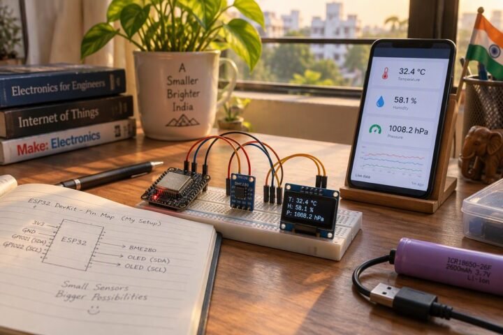
An ESP32 that wakes, reads a sensor, sends the result and goes back to deep sleep can run on a battery for weeks; the same board left awake runs for hours. This guide explains what deep sleep turns off, how to wake the board, what survives the sleep, and how to budget the battery before you build.
Status: written from Espressif’s sleep-mode documentation. The code has not been run on a board here, and the battery-life figures are a worked example with assumed numbers, not measurements.
What deep sleep switches off
Espressif’s documentation describes deep sleep as powering down the CPUs, most of the RAM and the digital peripherals. Only the RTC controller, the ULP coprocessor and the RTC memory stay powered. The Wi-Fi and Bluetooth radios are off in both light sleep and deep sleep. Because most of the chip is off, waking from deep sleep restarts the program from the beginning, so setup() runs again.
Light sleep is the gentler mode: the CPU pauses and resumes where it stopped, at a higher sleep current. For a sensor that reports every few minutes, deep sleep is the usual choice; for a robot that must react quickly to a button, light sleep or an external wake pin may suit better.
Ways to wake the board
| Wake source | What it does | Notes |
|---|---|---|
| Timer | Wakes after a set time in microseconds | Set with esp_sleep_enable_timer_wakeup(); the simplest option |
| ext0 | Wakes on one RTC GPIO level | Keeps the RTC peripherals powered, which costs a little more current |
| ext1 | Wakes on a group of RTC GPIOs | All pins in the group share one wake level; works with the RTC peripherals off |
| Touch pad | Wakes on a touch event | Enabled with esp_sleep_enable_touchpad_wakeup() |
| ULP coprocessor | A tiny program checks a sensor while the CPU sleeps | For advanced designs; behaviour differs between chip versions |
Only RTC-capable pins can wake the chip, and after a wake the pin is configured for RTC use, so reconfigure it before using it as a normal input. The exact rules differ between the original ESP32, the S3 and the C3, so check the page for your chip and ESP-IDF version.
What survives the sleep
Ordinary variables are lost, because the RAM is off. Variables marked RTC_DATA_ATTR are placed in RTC memory and keep their value across deep sleeps, which is how the common wake-count example works. They are lost when power is removed or the board is reset by the button.
// Untested outline for the Arduino core.
RTC_DATA_ATTR int bootCount = 0;

void setup() {
  bootCount++;
  // read the sensor and send the reading here
  esp_sleep_enable_timer_wakeup(10ULL * 60ULL * 1000000ULL); // 10 minutes in microseconds
  esp_deep_sleep_start();
}

void loop() {}   // never reached
A battery budget with assumed numbers
Battery life is capacity divided by average current, and the average has to include the sleep time. Here is an illustrative example, not a measurement. Assume a 2000 mAh cell with 75 percent usable, which is 1500 mAh. Assume the board draws 80 mA for 10 seconds while it wakes, reads and sends, then 1 mA while asleep for the other 590 seconds of a 10-minute cycle.
| Part of the cycle | Time | Current | Charge |
|---|---|---|---|
| Awake | 10 s | 80 mA | 800 mA·s |
| Asleep | 590 s | 1 mA | 590 mA·s |
| Total per cycle | 600 s | 1390 mA·s |
That is about 2.3 mA on average, so 1500 mAh lasts roughly 650 hours, or about 27 days. Left awake at 80 mA the same cell would last under 19 hours. The result moves a lot with the two assumptions that you must measure yourself: the real awake time, which Wi-Fi connection dominates, and the real sleep current.
Why the sleep current on your board may be far higher
The chip’s own deep-sleep draw is small, and the datasheet gives the figure for the bare chip. Most development boards add a USB-to-serial chip, a power LED and a linear regulator that all keep drawing current while the ESP32 sleeps, so the board as a whole can draw far more than the chip. For a battery project, measure the whole board with a multimeter in series with the supply, and consider a board designed for low power or removing the LED.
Making the awake time short
- Connect fast. The radio connection is the longest part of the awake time. Reusing a stored channel and address can shorten it; see the Wi-Fi notes in the ESP-IDF documentation.
- Send once and sleep. Gather the readings first, then transmit one message.
- Power the sensor from a GPIO or switch it off during sleep if it draws current when idle.
- Check the supply. Radio bursts draw current peaks; see the brownout fix page if the board resets on wake.
A test plan
- Measure awake current and time with the multimeter or a USB power meter that logs.
- Measure sleep current over a minute, after the board has settled.
- Compute your own budget with the numbers you measured, using the battery budget method.
- Run it for a day and compare the battery voltage drop with your prediction.
- Record your results with photos of your set-up. They are what make this guide yours.
For board pins and which ones are RTC-capable, see the ESP32 pinout guide, and for battery sizing in general see the robot battery guide.
Sources: Espressif ESP-IDF Sleep Modes documentation and Arduino-ESP32 deep sleep API. Last reviewed November 2026. Written, checked and maintained by Jignesh Panchal.