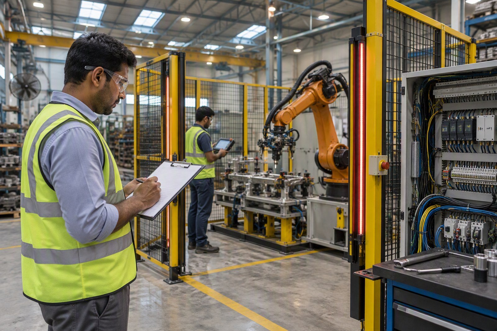
The cell is installed. The robot is anchored, the fence is up, the panel is wired, and the integrator wants the acceptance sheet signed.
Before you book the install, check the building itself: robot cell site readiness in India covers the floor loads, anchors, 3-phase supply and earthing the cell will actually need.
Nothing has yet proved that the cell stops when a gate opens, that it holds cycle time on a real part, or that your second shift can recover it after a jam. Commissioning is where those proofs happen, in order, each recorded before the next begins.
The sequence below runs from mechanical completion to full rate. Robot and integrator are already chosen — how the robot was chosen and how the integrator was selected are separate decisions — and this is written for the engineer who signs.
A cell is commissioned when it has been proved to stop, reject and recover
Commissioning is not a visit by a technician. It is a sequence of gates: mechanical completion, energisation, safety validation, production acceptance. Each gate produces a record and a signatory, and the next gate opens only when the previous record exists.
Factory acceptance proves the cell was built correctly. Site acceptance proves it survived transport, installation and your part presentation. Re-test what changed on site; carry the factory records forward.
Name the attendees in the contract: the integrator’s commissioning engineer, the robot OEM’s engineer if the safety configuration is OEM-owned, your maintenance engineer, safety officer, production supervisor and quality inspector.
Mechanical completion: sign it before anything is energised
Mechanical completion is a separate certificate, not a paragraph in the acceptance report. Walk the cell with a torque wrench and a drawing, not a clipboard.
- Base: grout cured, anchor torque to the maker’s specification, flatness checked, cable entries sealed.
- Guarding: posts plumb, panel gaps even, gates aligned, floor gap closed, no sharp edges at hand height.
- Layout: robot envelope clear of walkways, panel access for maintenance, fire exits unobstructed.
- Services: air pressure and flow at the gripper, dryer and drains working, filtration to the gripper maker’s ISO 8573-1 class, isolator lockable.
- Cabling: dress pack clear through the envelope, power and signal separated, fence and base bonded.
Re-check the robot-to-fixture datum after grouting and after the conveyor is aligned. Cells are often built robot-first and conveyor-later; the datum moves with the grout.
Pre-energisation checks on a 415 V Indian supply
Isolate, lock off and prove dead. Then look for backfeeds: the UPS, the drives’ DC bus, the robot controller’s internal supply and any battery-backed safety controller.
Test to IEC 60204-1 section 18: protective bonding continuity, insulation resistance at 500 V DC with a minimum of 1 MΩ, and residual voltage below 60 V within five seconds. Disconnect drives and electronics first; a megger will find them.
Measure earth electrode resistance in dry weather; record it. Bond fence, robot base and panel to the same earth. Check phase sequence at the incomer and at every conveyor motor: a generator changeover can change phase sequence, and the first symptom is a drive that will not start.
Log the supply for a week first. The voltage at 2 pm and at 2 am differs, and so does the air dew point in July; neither is a programming fault, but both get blamed on the program.
Power-up order: control power, then safety, then motion
Bring the cell up in stages, with a written step list and a second person at the isolator.
- Control power only. Drives isolated. Boot the robot controller, PLC, HMI, safety controller and network; clear every diagnostic before going further.
- Input and output checkout. Force every sensor and button, watch every solenoid and lamp, and fix faults at the terminal, not in the program. Settle whether the cell PLC or the robot controller owns the sequence before debugging a handshake neither side owns.
- Safety circuit. Test the logic with drives isolated, then with drives enabled at reduced speed. The second test proves the contactors actually drop.
- Motion. Mastering check, axis and software limits, brake release, jog in teach mode with the enabling device. Back up parameters immediately.
- Handshakes. Upstream and downstream signals, conveyor, vision, scanner zones. Simulate the other machine before you connect to it.
Do not energise drives to see if it moves. The first motion should be expected, slow and under an enabling device.
Safety function verification: measure the stop, not the certificate
The risk assessment names the safety functions and the performance level each needs. ISO 10218-2:2025 covers the cell, ISO 13849-1:2023 the safety-related control system, ISO 13855:2024 the distance calculation; the standards that apply in Indian plants cover the rest.
Test worst case: full speed, rated payload, least favourable pose, brakes hot. Measure stopping time and distance, repeat, use the worst result, and recalculate the minimum distance from it. If the fence or curtain sits inside that distance, move it or slow the robot.
Where the design allows, inject a single fault — a contactor that fails to drop, an earth fault on a safety input — and record the response. That is how a Category 3 circuit is proved to detect the fault. An OEM certificate covers the robot, not your guard switches, relays and reset logic.
| Safety function | Test at the cell | Pass criterion | Record kept |
|---|---|---|---|
| Emergency stop | Every button and rope, each position | Motion stops, drives isolated, reset required | ID, stop time, distance |
| Gate interlock | Open each gate at full speed | Hazard stops before access; lock releases only after stop | Gate ID, stop and release times |
| Light curtain or scanner | Test piece at each zone edge and in muting | Detection stops the cycle; muting follows the part | Zone, test piece size, response time |
| Enabling device | Release and over-press in teach mode | Motion stops in both positions; no automatic restart | Device ID, observed function |
| Protective stop and STO | Command from PLC, safety device and robot panel | Stop category as designed; STO channels separate | Channel check, stop time |
| Brake and holding | Static hold at rated payload; dynamic stop | No drift beyond stated limit; stop within layout | Load, drift, distance |
| Speed and separation | Cobot or scanner at closest approach | Speed and distance within assessment limits | Method, worst case |
Dry runs: jog, step, then automatic at reduced speed
Teach mode first, with the enabling device and reduced speed. Watch the dress pack, gripper, fixture, fence and air lines through the full envelope; a cable that touches a guard at one corner fails in month three, not on the day.
Step the sequence, then run it continuously at reduced speed. Simulate what the cell will see: no part, double part, jam, vacuum loss, upstream stop, downstream full, power dip, and an emergency stop at each point in the cycle. Write the recovery procedure and make your operator perform it, not the integrator.
Measure cycle time over thirty to fifty cycles and record the minimum and maximum, not the best. A cell that makes rate once is not at rate.
Trial batch: accept on the worst shift, not the best hour
Write the runoff into the contract before the cell arrives: a typical acceptance run is 200 to 500 parts, or four to eight hours of continuous running, whichever comes first. That is a planning figure, not an industry standard.
Quality approves the first-off and sets the in-process checks; the capability figure comes from your quality plan, not the integrator’s brochure. Reason-code every stoppage with its duration and who fixed it. Accept on rate, quality, availability, safety evidence and documents; if any one fails, use the retest window rather than signing “subject to completion”.
Ramp-up: 50, 80, 100 per cent, with the numbers watched
Hold each stage for a defined number of shifts before increasing speed. Watch OEE, mean time between failures, operator interventions and scrap. Train operators, maintenance and supervisors separately, and assess competence rather than attendance.
Keep critical spares on site before the runoff, not after the first breakdown. The first thirty days tell you whether you have a design problem or a training problem, and the log is the only way to tell them apart.
The record pack you keep after acceptance
The acceptance sheet is a summary. The evidence behind it is what an inspector, an insurer or your maintenance team will ask for in two years.
| Stage | What it proves | Record kept | Signed by |
|---|---|---|---|
| Mechanical completion | Built to drawing, guards in place | Checklist, torque values, as-builts | Integrator, maintenance |
| Electrical | Supply, earthing, insulation sound | Test sheet with measured values | Contractor, plant |
| Safety validation | Functions stop within calculated distance | Report, stop times, PL verification | Integrator, safety officer |
| Dry run | Sequence and recovery work | Log with faults and fixes | Commissioning engineer, production |
| Trial batch | Good parts at rate | Runoff report, first-off, stoppage log | Quality, production |
| Site acceptance | Contract performance met | SAT certificate, training, backups | Authorised signatory |
The Occupational Safety, Health and Working Conditions Code, 2020, in force since 21 November 2025 in place of the Factories Act, puts the duty to keep the plant safe and to fence dangerous machinery on the occupier; the fencing duty sits in that Code, while the state factory licence and plan approval sit with your inspectorate. The validation report is evidence, not a transfer of that duty.
Keep the risk assessment beside the validation report: one says what could happen, the other says what you did about it, and who signed it off.
Keep the technical file for the life of the cell. Register software licences and warranties in your name, with warranty starting at site acceptance. Build the routine from the robot maintenance checklist in week one.
For planning, allow ₹1,00,000–₹4,00,000 for independent validation of a single cell and ₹25,000–₹75,000 for a stopping-time measurement visit. These are illustrative planning ranges, not quotations. The production lost during a slow ramp is often larger than both; the industrial robot cost guide covers the rest of the budget.
Sign the evidence, not the visit.
Frequently asked questions
How long does robot cell commissioning take in India?
It depends on the process, not the robot. A single-robot tending cell with a proven process often takes one to three weeks from mechanical completion to acceptance; welding or inspection cells take longer because the process must be qualified.
Who should sign the robot cell acceptance sheet?
The plant's authorised signatory, after maintenance, safety, quality and production have signed their evidence. A commissioning engineer's sign-off is a technical record, not contract acceptance.
Can we start production before the safety functions are validated?
No. Teach-mode work under an enabling device is one thing; automatic production is another. Running automatic before validation exposes the occupier's duty under the OSH Code, 2020.
What stopping time should go into the record?
The worst measured stop at full speed, rated payload and least favourable pose, repeated to show the spread, with brakes hot. Use it, not the catalogue figure, for the ISO 13855 distance.
Is third-party safety validation required in India?
No single national rule names a validator for every cell. The duty sits with the occupier; the practical question is whether you hold credible evidence. Independent validation suits high-risk cells, or where a customer or insurer asks.
Which records should we keep after commissioning?
The validation report, as-built and guard drawings, electrical test sheets, program backups, training records, the acceptance certificate, spares list and warranty dates. Keep them for the life of the cell.
Where the audit ends, validation begins: how to prove the cell stops in time, using measured stopping time and the ISO 13855 distance calculation.
Sources and further reading
- The Factories Act, 1948 — full text as it stood before repeal, Directorate General of Mines Safety
- IBF Solutions — new standards for industrial robots, EN ISO 10218-1 and -2
- CEM4 — ISO 13855:2024 on positioning safeguards against approach speeds
- Knox Thomas — EN 60204-1 section 18, verification and testing for machines