Vision-guided robotics fails at calibration before it fails at detection. The camera usually sees the part correctly; the robot simply does not know where the camera is.
This guide covers the camera arrangements, the four calibrations a working cell needs, the error budget that decides your tolerance, the latency chain nobody quotes, and what a vision-guided cell costs in India.
What vision guidance actually changes
A blind robot repeats a taught point. A vision-guided robot computes a new point each cycle from what the camera sees. That single change moves the requirement from mechanical repeatability to calibration accuracy, and it moves the failure mode from “missed the fixture” to “consistent 3 mm offset in one corner of the field of view”.
Use vision when part position varies, when fixtures are too expensive, when parts arrive in a bin, or when you need to inspect at the same time. Do not use it to compensate for a robot that cannot repeat, or for parts that a simple mechanical stop would locate in two seconds.
| Arrangement | Camera position | Best for | Main weakness |
|---|---|---|---|
| Fixed, looking down | Mounted above the pick area | Conveyor pick, single station | Occlusion by the robot arm |
| Eye in hand | On the wrist, moves with the tool | Bin picking, large work envelope | Calibration drifts with tool changes |
| Fixed with a moving conveyor | Above the belt | Tracking on the fly | Encoder sync and latency |
| 2D fixed, 3D fixed | Above the station | Flat parts, stack picking | 3D adds cost and setup time |
| Line scan | Across a moving belt | Continuous inspection | Needs clean, constant motion |
The four calibrations
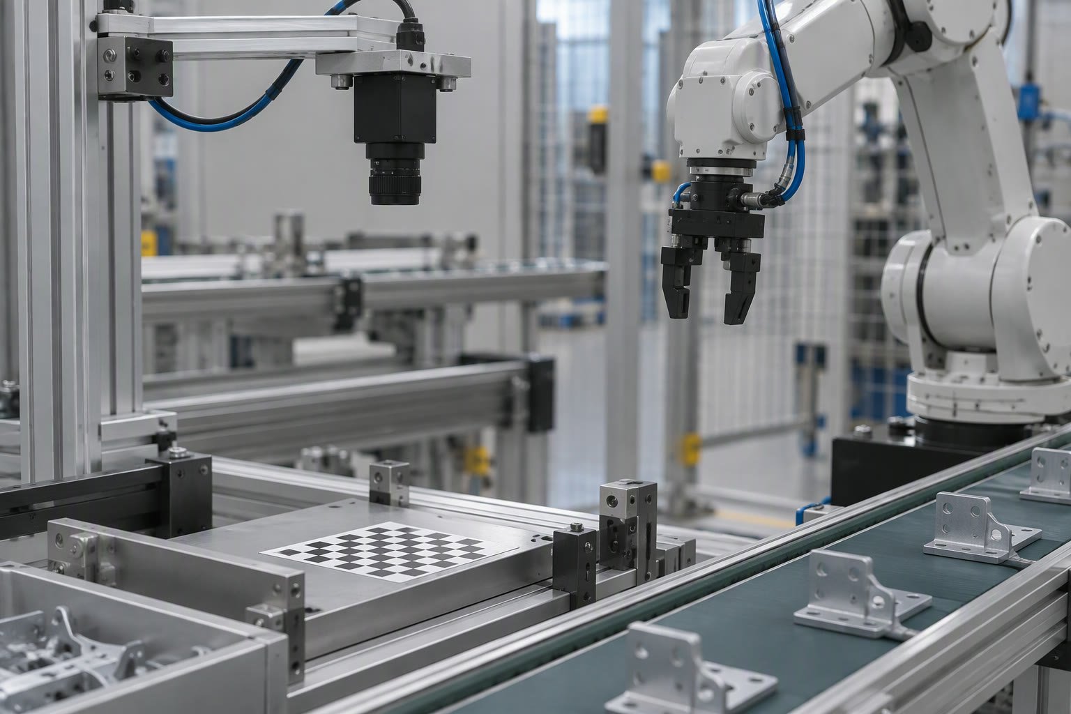
- Camera intrinsics: focal length, principal point and lens distortion. Done once per lens with a calibration target. Redo it if the lens or focus changes.
- Hand-eye (extrinsics): where the camera sits relative to the robot flange or the cell base. This is the calibration that decides pick accuracy.
- TCP: where the tool centre point really is. A wrong TCP looks exactly like a vision error, which is why you calibrate the tool first.
- Conveyor or encoder: how many millimetres of belt travel equal one encoder count, and the sign of the direction.
Do them in that order. Calibrating hand-eye with a wrong TCP bakes the tool error into the camera transform, and every later fix makes the number worse.
Hand-eye calibration without the matrix algebra
The classic formulation is AX = XB: the robot moves, the camera sees the same target from a new pose, and the solver finds the transform that explains both. You do not need to derive it, but you do need to know what makes it good or bad.
- Use a target that the camera sees sharply at the working distance, not a printout taped to a wall.
- Collect at least 10 to 15 poses, not the minimum your toolkit accepts.
- Spread the poses: rotation about all three axes, and translation across the whole working volume.
- Keep every pose inside the region where parts will actually be picked.
- Check the residual error the solver reports, and re-shoot the worst pose rather than accepting a bad set.
A calibration that reports a small residual but only used poses in one corner will pass the check and fail in production. Spread matters more than pose count.
Build an error budget before you promise a tolerance
Every element in the chain contributes error. Add them in quadrature rather than pretending the largest one is the total, and check the sum against the clearance you actually have.
| Source | Typical contribution | How to reduce it |
|---|---|---|
| Robot repeatability | From the datasheet, often ±0.02 to ±0.1 mm | Choose a robot rated for the accuracy, not only the payload |
| TCP calibration | 0.2–1 mm if done quickly | Use a fixed reference point and several orientations |
| Hand-eye calibration | 0.3–2 mm depending on pose spread | More poses across the full volume |
| Pixel resolution at the part | 0.1–1 mm per pixel | Narrower field of view or a higher-resolution sensor |
| Part pose estimate | 0.2–3 mm for a 2D centroid | Use features, not a blob centroid |
| Thermal drift | 0.1–0.5 mm over a shift | Warm up, then calibrate; re-check mid-shift |
| Fixture or belt slip | Unbounded | Fix the mechanics before adding vision |
If the sum is larger than the insertion clearance, vision will work in the demo and jam in production. State the budget in the acceptance test and measure it with a test part at the edges of the field of view, not just in the centre.
Part presentation decides more than the camera
Structured presentation, where parts sit in a known orientation, needs a cheap 2D camera and a simple centroid. Random presentation in a bin needs 3D sensing, segmentation, collision-aware grasp planning and a longer cycle. The gap in cost and engineering time is large.
- Flat parts on a mat: 2D camera, colour or contour segmentation, one calibration.
- Parts in a single layer with overlap: 2D plus a grasp-point rule, or a low-cost 3D sensor.
- Parts in a deep bin: 3D sensor, bin-picking software, suction or magnetic gripper, collision checks.
- Parts on a moving belt: encoder tracking and a prediction of where the part will be when the robot arrives.
- Shiny or transparent parts: polarisation, structured light or a change of part presentation before more software.
The latency chain
Vision is not instantaneous, and on a moving line the delay turns into a position error. The chain runs from the trigger to the robot starting to move, and every link adds time.
- Trigger and handshake with the PLC.
- Exposure time, which must be short enough to freeze motion.
- Frame transfer over USB or GigE.
- Pre-processing and inference.
- Coordinate transform and the robot command.
- Robot acceleration to the intercept point.
At 200 mm/s of belt speed, every 50 ms of delay is 10 mm of travel. Either measure the chain and compensate with the encoder, or slow the belt. Buying a faster camera does not fix a slow handshake.
Lighting and lens choices that keep the software simple
A part that is easy to segment saves weeks of model tuning. Before adding a network, make the image boring: even illumination, a background that is not the same colour as the part, and a lens that fills the frame with the working area rather than half the factory.
For shiny metal, try a dome or coaxial light to remove hot spots. For dark parts on a dark belt, backlight or a coloured filter that separates the two. For parts that move, strobe the light so exposure can be short without a huge aperture.
What a vision-guided cell costs in India
These are planning ranges for budgeting, not quotations. Integrator day rates, sensor choice and the amount of software work move the total a long way, so get at least three quotes on a written specification.
| Item | Planning range | Notes |
|---|---|---|
| 2D industrial camera, lens, cable | ₹35,000–₹1,20,000 | Resolution drives the price more than brand |
| 3D sensor for bin picking | ₹2,00,000–₹6,00,000 | Software licence often separate |
| Lighting and controller | ₹15,000–₹80,000 | Bigger field of view, bigger bill |
| Vision PC or edge computer | ₹60,000–₹2,00,000 | GPU only if inference needs it |
| Calibration and integration | ₹1,00,000–₹4,00,000 | The part most often under-budgeted |
| Robot-side interface | ₹25,000–₹1,50,000 | Socket, fieldbus or vendor vision option |
Add the robot, gripper, guarding and safety validation on top. A vision system rarely exceeds a third of the cell cost, but it is usually the part that decides whether the project finishes on time.
When vision guidance does not pay
- The part is always in the same place and a mechanical stop costs ₹5,000.
- The tolerance is looser than the robot’s repeatability, so the camera adds nothing.
- The cycle is already at takt and the extra 300 ms per pick breaks it.
- Part variation is so large that no single setup covers it, and the process needs fixing first.
- Nobody on site can maintain calibration and lighting after handover.
A commissioning sequence that converges
- Mount the camera rigidly and check the mount does not flex when the robot moves.
- Set focus and aperture at the working distance, then lock them.
- Calibrate TCP against a fixed point.
- Capture intrinsics, then hand-eye with spread poses.
- Verify with a target at five points across the field of view.
- Run 50 picks from a fixed presentation and log the error.
- Add part variation, then motion, then production speed.
- Write down the residuals and the calibration date.
Each step should hold before the next begins. A cell that passes 50 picks at the centre and then fails at the edges has a calibration spread problem, not a detector problem, and no amount of model tuning will fix it.
Mistakes that cost the most
| Mistake | Consequence |
|---|---|
| Calibrating before the tool is final | Every result shifts when the gripper changes |
| Poses in one corner of the volume | Small residual, large error at the edges |
| Camera on a flexing bracket | Accuracy changes with robot speed |
| Ignoring latency on a moving belt | Consistent offset that grows with speed |
| Tuning the model to hide a lighting fault | Works at noon, fails on the night shift |
| No re-check after a shift | Thermal drift goes unnoticed until scrap appears |
| No acceptance test at the edges | Dispute with the integrator, no evidence |
Related: robot vision cameras, machine vision lighting, YOLO object detection, TCP calibration, robot cell layout.
What is vision-guided robotics?
A robot that uses a camera to find the part and compute a new pick or place point each cycle, instead of repeating a taught position. Accuracy depends on camera, tool and hand-eye calibration.
What is hand-eye calibration?
The transform between the camera and the robot. It is solved from several robot poses with the camera observing the same target, and its quality depends on spreading those poses across the working volume.
Why is my vision-guided robot accurate in the centre but not at the edges?
Usually a calibration collected from poses in one region, lens distortion that was not corrected, or a twisted camera mount. Recalibrate with spread poses and verify at five points across the field of view.
Do I need a 3D camera for bin picking?
Yes for parts in a deep bin. A 2D camera can handle single-layer parts with known orientation, but random piles need depth, segmentation and collision-aware grasp planning.
How much does a vision-guided robot cell cost in India?
The vision package commonly plans at ₹2 lakh to ₹10 lakh depending on 2D or 3D sensing, lighting, compute and integration. The robot, gripper and safety come on top, so get written quotes.
Every vision guided system starts with camera calibration before a single pick is attempted.
Where part orientation is fixed, ArUco markers are often enough to guide the gripper.
Bin picking and palletising usually need depth, and the depth camera guide covers which technology survives shiny parts.
The arm itself still has to be sized correctly, which this industrial robot buying guide explains step by step.
When the robot must pick what it inspected, combine this with an inspection specification.
The interface sets the latency budget for the whole loop, which our guide to camera interfaces breaks down per cable type.
Vision accuracy starts with the optics, and our lens selection guide covers the numbers that set it.
Code reading is often the first vision job in a cell, and the OCR and code reading guide covers the traceability link to robot guidance.
See our 3D bin picking guide for the practical limits of depth sensing in a mixed bin.
Sources and further reading
- ISO 10218 — robot system safety and integration requirements.
- OpenCV — camera calibration and computer vision documentation.
- Cognex — vision system and lighting application notes.
- Universal Robots — hand-eye calibration guidance for cobot vision.