I2C pull-up resistors must be small enough for the bus signal to rise quickly and large enough that a device can still pull the line low. For a 3.3 V bus at 400 kHz with about 100 pF of bus capacitance, that window is roughly 1 kOhm to 3.5 kOhm, so 2.2 kOhm is a common choice.
Key takeaways
- I2C devices only pull the SDA and SCL lines low, and the pull-up resistors bring them high again, so the rise time depends on resistance times bus capacitance.
- The rise time from 30 percent to 70 percent of the supply is about 0.8473 x R x C.
- Fast mode (400 kHz) commonly allows a rise time of up to 300 ns, and standard mode (100 kHz) up to 1000 ns.
- The minimum resistor value comes from the current a device can sink, commonly 3 mA at 0.4 V low level.
Why I2C Needs Pull-Ups
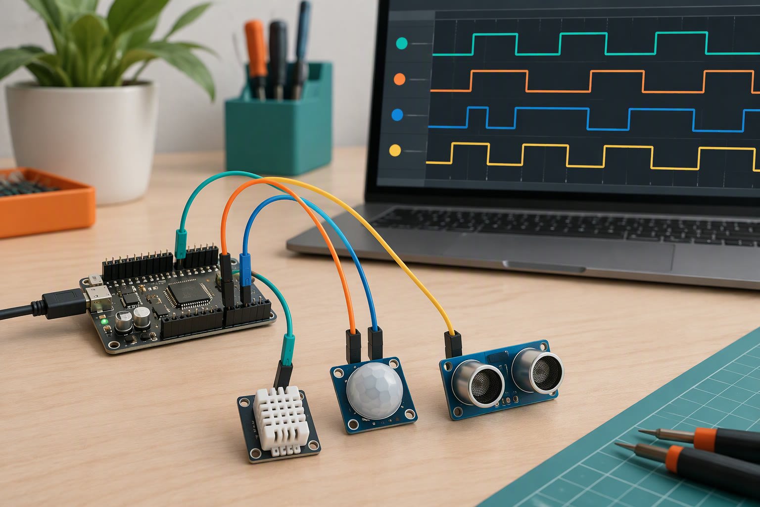
A pull-up resistor is a resistor connected from a signal line to the supply voltage, so that the line sits high when nothing pulls it down. I2C uses two lines, SDA (data) and SCL (clock), and every device on them can only pull a line low or let it go. Nothing actively drives the line high, so without pull-ups the bus never goes high and does not work.
An overview of how I2C compares with SPI and UART is in I2C, SPI and UART in robotics. The default I2C pins on each board are in the Arduino Uno pinout for robotics and the ESP32 pinout for robotics.
Open-Drain Basics
Open-drain means a pin can connect its line to ground or leave it disconnected, but cannot connect it to the supply. This arrangement lets many devices share one wire without fighting: if any device pulls the line low, the line is low. It also means two devices with different supply voltages can share a bus through level shifting, as long as the pull-up goes to the right voltage.
The resistor value is therefore a trade-off. A smaller resistor gives a faster rise and a stronger high level, but a device pulling low must sink more current. A larger resistor saves current but makes the rise slow and rounded, and at higher speeds the data gets corrupted.
RC Rise Time Calculation
The line is a resistor charging the bus capacitance, so it rises like an RC circuit. Bus capacitance is the total capacitance of wires, pins and device inputs on the line. The I2C specification measures rise time between 30 percent and 70 percent of the supply, which works out to:
t_rise = 0.8473 x R x C- Maximum pull-up:
R_max = t_rise_max / (0.8473 x C) - Minimum pull-up:
R_min = (Vdd - V_OL) / I_OL, where V_OL is the maximum low level (commonly 0.4 V) and I_OL the sink current (commonly 3 mA).
Check the exact numbers in the I2C specification and in your devices’ datasheets, since limits differ between modes and parts.
Worked Example at 400 kHz
Assumptions: 3.3 V supply, fast mode with a maximum rise time of 300 ns, estimated bus capacitance of 100 pF (short wires and a few devices), V_OL of 0.4 V and I_OL of 3 mA.
Upper limit
- 0.8473 x 100 pF = 0.8473 x 100e-12 = 8.473e-11
- R_max = 300e-9 / 8.473e-11 = 3541 ohm, about 3.5 kOhm
Lower limit
- R_min = (3.3 – 0.4) / 0.003 = 2.9 / 0.003 = 967 ohm
So any value from about 1 kOhm to 3.5 kOhm fits. Pick 2.2 kOhm:
- t_rise = 0.8473 x 2200 x 100e-12 = 1.864e-7 s, about 186 ns, under 300 ns
- Current when low = (3.3 – 0.4) / 2200 = 1.32 mA, under 3 mA
| Case | Calculation | Result |
|---|---|---|
| R_max at 100 pF, 400 kHz | 300 ns / (0.8473 x 100 pF) | 3.54 kOhm |
| R_max at 200 pF, 400 kHz | 300 ns / (0.8473 x 200 pF) | 1.77 kOhm |
| R_min at 3.3 V | 2.9 V / 3 mA | 967 ohm |
| R_min at 5 V | 4.6 V / 3 mA | 1.53 kOhm |
| 4.7 kOhm at 100 pF | 0.8473 x 4700 x 100 pF | 398 ns, too slow for 400 kHz |
| 4.7 kOhm at 100 pF, 100 kHz | limit 1000 ns | 398 ns, fine |
The last rows explain why 4.7 kOhm works on many beginner projects at 100 kHz and fails at 400 kHz. If the capacitance rises to 200 pF, 2.2 kOhm gives 0.8473 x 2200 x 200e-12 = 373 ns, which is too slow for fast mode. You would need 1.5 kOhm or lower, which is above the 967 ohm minimum.
Multiple Devices on One Bus
Every device adds input capacitance, and the wires add more, so a longer bus with more devices needs a smaller pull-up or a slower clock. Resistors on each breakout board are also in parallel with each other, so the effective pull-up falls as you add boards.
Example: four modules each with an onboard 10 kOhm pull-up on SDA. Four equal resistors in parallel give 10 / 4 = 2.5 kOhm, which is inside the 1 to 3.5 kOhm window. Ten such modules would give 1 kOhm, close to the 967 ohm minimum at 3.3 V, so you would need to remove some pull-ups. If a bus has devices at the same address, a multiplexer such as the TCA9548A I2C multiplexer splits it into separate channels, each with its own load. A servo driver such as the PCA9685 servo driver is a typical device sharing the bus, as in the servo robot arm with record and playback on Arduino.
Common Module Mistakes
- Not knowing that a breakout board already has pull-ups, so adding more makes the total too low.
- Removing all pull-ups, so the bus has none.
- Using different supply voltages on devices without a level shifter, or pulling up a 3.3 V device to 5 V.
- Long wires between modules, which add capacitance, and unshielded cables beside motor wires.
- Running 400 kHz when the wiring is only good for 100 kHz.
A data logger such as the temperature data logger with DS18B20, DS3231 and SD card adds an I2C clock module to a project that also uses other wiring, so it is a good place to practise checking pull-ups. The wiring checker flags pin conflicts on ESP32 and Arduino Uno.
How to check this yourself
- List every device on the bus and read the datasheet for its maximum bus speed and its V_OL and I_OL figures.
- Check each breakout board’s schematic or photos for onboard pull-up resistors, and compute their parallel value.
- Estimate bus capacitance from the datasheets (device pin capacitance) plus wiring, or measure it if you have an LCR meter.
- Compute R_max from your rise-time limit and R_min from your supply voltage and sink current, and check that the combined pull-up lies between them.
- If you have an oscilloscope, look at SDA and SCL and check the rise from 30 to 70 percent of the supply against your limit.
Quick checklist
- Choose a speed mode: 100 kHz or 400 kHz.
- Estimate bus capacitance and compute R_max.
- Compute R_min from the supply voltage and 3 mA sink current.
- Count the onboard pull-ups and calculate their parallel value.
- Pick a value inside the window, and verify with a scope or by reliable operation.
Frequently asked questions
What value of pull-up resistor should I use for I2C?
Common choices are 4.7 kOhm at 100 kHz and 2.2 kOhm at 400 kHz on short buses at 3.3 V or 5 V. The right value depends on bus capacitance, speed and supply voltage, so compute the window from your own numbers and check your device datasheets.
Do I need external pull-ups with Arduino or ESP32?
Often yes. The internal pull-ups on these chips are weak and usually too high in resistance for reliable I2C beyond short wires at low speed. Many breakout modules include pull-ups already, so check the board before adding more.
What happens if the pull-up resistor is too large or too small?
Too large, and the signal rises slowly, so data at higher speeds is corrupted and devices may miss bits. Too small, and a device cannot pull the line low to a valid level, because it would have to sink more than its rated current.
Related reading
- Robotics Learn hub, for more bus and wiring guides.
About the author and how this is kept accurate
Written, checked and maintained by Jignesh Panchal of Jaadu Digital. Figures in worked examples come from the stated assumptions, not from a bench test of our own. Read the editorial standard, follow the author on LinkedIn, or send a correction. Last reviewed: November 2026.