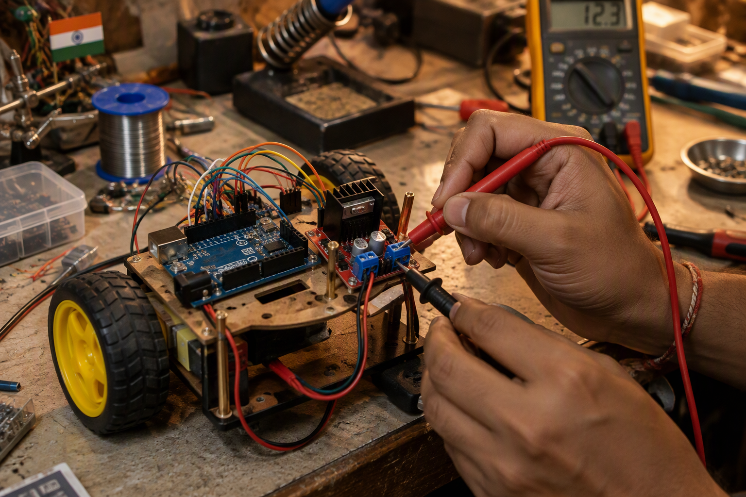
Most Arduino robots that “just stopped working” have not broken — they have lost a ground, browned out, or been uploaded to the wrong board. The order you check in decides whether you find that in ten minutes or two hours. This is the sequence that works: prove power, prove ground, prove the driver, prove the code, then blame the sensor. Fourteen checks, each with the measurement that settles it.
It is written for a differential-drive robot with an Arduino, a motor driver module and a handful of sensors, but the order holds for almost anything you have built on a breadboard. The rule underneath all of it: a fault has one cause, and you find it by halving the possibilities, not by changing code until something works.
The three questions that split the fault in half
Before touching a wire, answer these. Each answer removes half the remaining possibilities.
- Does the onboard LED blink and does the code upload? If yes, the microcontroller and the USB path are alive, so the fault is downstream — power distribution, driver, wiring or sensors.
- Does the robot behave differently on USB power than on battery? If it works on USB and dies on battery, you have a supply problem, not a logic problem.
- Does the serial monitor print anything? If the code runs but prints nothing, your
Serial.begin()baud rate does not match the monitor, or the code never reached that line.
If all three answers are “no”, stop and check the cable and the port. A charge-only USB cable is a genuinely common cause of “the board is dead” and costs nothing to rule out.
Symptom to cause, in one table
| Symptom | Most likely cause | First test |
|---|---|---|
| Nothing happens at all | No power, or charge-only USB cable | Measure battery voltage at the board’s input pins |
| LED blinks, motors dead | Driver not enabled, or driver unpowered | Measure driver VCC and VM pins separately |
| Arduino resets when motors start | Brownout from inrush current | Watch the 5 V rail with a multimeter during startup |
| One wheel turns, one doesn’t | Wiring, driver channel, or a dead motor | Swap the two motors at the driver outputs |
| Robot drives in a curve | Motor mismatch, wheel slip or caster drag | Run both motors at the same PWM with wheels raised |
| Motors twitch or buzz | PWM in the deadband, or a loose ground | Raise PWM until motion starts, then check grounds |
| Sensor readings jump | Timing, interference or supply noise | Print raw values with the motors off, then on |
| Works for a minute, then stops | Driver thermal shutdown or battery sag | Touch the driver heatsink and measure the pack under load |
Checks 1 to 5: power and ground
1. Measure the battery under load, not open-circuit
A pack that reads 7.4 V with nothing connected can sag to 5.5 V the moment both motors start. Measure at the board’s input pins with the robot commanded forward and the wheels on the floor. If the reading drops more than about a volt, the battery or the wiring is the fault. A 9 V PP3 battery will run the Arduino and fail completely at driving two gear motors — that is not a bug, it is chemistry.
2. Prove the grounds are common
The motor supply and the logic supply must share a ground, and it must be a real wire, not a shared breadboard rail that stops halfway. With the multimeter on continuity, check from the Arduino GND pin to the driver GND pin, then to the battery negative. If any of those reads open, nothing else you do will behave predictably.
3. Look for brownout on motor start
If the Arduino resets the instant the motors spin, the supply is collapsing below the brownout threshold. Fixes, in order of effort: separate the motor supply from the logic supply, add a large electrolytic capacitor across the driver’s supply pins, shorten and thicken the battery leads. The power guide covers the arithmetic for choosing the capacitor and the pack.
4. Know which source powers what
On many builds the Arduino is powered from USB while the motors run from the battery. That works until you unplug the laptop and the logic loses power while the motors keep a supply. Decide deliberately: one source for everything with a proper regulator, or two sources with a common ground. The buck converter guide shows the regulator side.
5. Check that the wires can carry the current
Jumper wires are rated for signal current, not stall current. Two motors stalling at 1.5 A each through a breadboard and thin dupont leads will drop volts and heat connectors. If the robot works on the bench and fails under load, move the motor circuit to screw terminals and thicker wire before changing anything in software.
Checks 6 to 8: the motor driver
6. Confirm the driver is actually enabled
The L298N has an enable jumper per channel; the TB6612 has a standby pin that must be driven high. A driver with no enable looks exactly like a driver with no power. Measure the enable pin while the code commands forward — it should be high, or pulsing if you are using PWM on it. The L298N versus TB6612 comparison lists the pin differences that catch people.
7. Check for thermal shutdown before you call it a code bug
A driver that works for forty seconds and then stops is usually protecting itself. Touch the heatsink — if it is too hot to hold, the driver is undersized for the stall current or the current limit is set too high. Lower the PWM, add airflow, or fit a driver rated above the stall current of both motors combined.
8. Swap the motors at the driver to isolate the channel
If one wheel does not turn, move the good motor to the dead channel and the dead motor to the good channel. If the fault follows the motor, the motor or its wiring is at fault. If it stays with the channel, the driver or the pin mapping is. Thirty seconds of swapping beats twenty minutes of reading code.
Checks 9 to 11: control and code
9. Reconcile the pin map with the board
Print the pin numbers your code believes it is using, then check them against the Uno pinout. The most common version of this bug is a pin that is also used by the serial port, or an analog pin used as a digital output without realising the numbering differs. One LED blink test per output pin settles it in a minute.
10. Find the blocking call
If the robot reacts late, ignores a sensor, or stutters, look for delay() in the main loop. While it runs, nothing else happens — no sensor reads, no motor updates. Replace it with a millis() comparison so the loop keeps turning. The IDE setup guide covers the serial monitor settings that make this visible.
11. Check the board and port selection in the IDE
A clone board selected as an Uno when it is actually a Nano, or a CH340 board with a missing driver, produces upload failures that look like a dead board. Confirm the port appears when you plug in, confirm the board type matches the silkscreen, and try a different cable before assuming hardware failure.
Checks 12 to 14: sensors and wireless
12. Fix the ultrasonic timing and voltage
An HC-SR04 returns a pulse whose length is the round-trip time, and on a 5 V board it also returns a 5 V echo. Read it with pulseIn() and a timeout, divide by 58 for centimetres, and throw away readings that arrive at the timeout. If the readings swing wildly, the jumping readings fix walks through the median filter.
13. Re-set the IR threshold in the actual room
Reflective IR sensors have a potentiometer and a habit of working on a white desk and failing on a dark floor. Put the robot on the surface it will actually run on, adjust the pot until the indicator LED switches cleanly, and then test under the lighting it will actually see. Sunlight through a window is enough to blind some modules.
14. Give the wireless module its own current
Bluetooth and Wi-Fi modules draw short bursts that the Arduino’s 3.3 V pin cannot always supply, which shows up as dropped connections or a module that works until the motors start. Power the module from a regulator that can deliver its peak, and check the logic level — a 3.3 V module fed 5 V logic will fail slowly and then permanently.
The sixty-second triage, in order
When you are stuck and the clock is running, do exactly this and nothing else:
- Battery voltage at the board, motors running.
- Continuity from Arduino GND to driver GND to battery negative.
- Driver enable pin state while commanding forward.
- Serial print of the sensor value with motors off, then on.
- Swap the motors at the driver.
Five measurements, no code changes. In most builds one of them names the fault outright.
When the robot is fine and the computer is not
A surprising share of “dead robot” reports are host problems: a charge-only USB cable, a COM port held open by another program, a driver that Windows replaced after an update, or an IDE that is still pointed at the previous board. If the onboard LED blinks when you press reset, the board is alive and the fault is between the board and the laptop. Try a second cable, a second port and a second computer before opening the robot.
What to write down while debugging
Keep a single line per test: what you changed, what you measured, what happened. Not for marks — for you, two days later. The pattern that emerges is usually that the fault appeared after a specific edit, and the log is what tells you which one. It also turns a viva question about debugging into an answer you already have.
Frequently asked questions
Why does my Arduino robot work on USB but not on battery?
The USB port supplies a stable 5 V at enough current for the logic, while the battery path either loses voltage in the regulator or sags under motor current. Check the regulator's dropout, the battery's discharge rating and the ground return before changing any code.
Why does my robot reset whenever the motors start?
Inrush current from the motors pulls the shared supply below the microcontroller's brownout threshold. Move the motors to their own supply, add a bulk capacitor at the driver, and make sure both supplies share a ground.
Why does my robot drive in circles instead of straight?
The two motors do not run at the same speed at the same PWM value, or one wheel is slipping. With the robot raised, run both at a fixed duty cycle and compare wheel revolutions; correct the difference in software with a trim factor, or fix the mechanical drag.
Why do my ultrasonic readings jump between numbers?
Missed echoes, angled surfaces, two sensors firing together, or noise on the supply. Read the echo with a timeout, discard timed-out values, take a median of five readings, and fire multiple sensors one after another rather than at the same time.
My code uploads but nothing moves. What do I check first?
The driver enable pin and the driver supply. A driver with no enable signal behaves exactly like a driver with no power, and both look like a code fault from the serial monitor. Measure the enable pin while the robot is commanded forward.
Sources
- Texas Instruments, L293x quadruple half-H drivers datasheet — enable inputs, current ratings and thermal behaviour of the same dual H-bridge architecture used on L298N modules.
- Arduino, Language Reference — millis, analogWrite and Serial behaviour used in the checks.
- Arduino, pulseIn() — echo timing and timeout behaviour for the ultrasonic check.
Related reading: HC-SR04 jumping readings · servo jitter fixes · stepper missing steps · how to power a robot · Arduino Uno pinout · obstacle avoiding robot build.