Battery internal resistance is the small resistance inside every cell and pack, and it makes the terminal voltage fall by current times resistance whenever the robot draws power. That voltage sag is why a battery that reads 11.4 V at rest can show about 10.4 V under an 8 A load, and why a pack can seem empty to your electronics while still holding charge.
Key takeaways
- Voltage sag equals load current times total internal resistance (V = I x R), so doubling the current doubles the sag.
- Cells connected in parallel divide the resistance; cells connected in series add it.
- The power lost as heat inside the pack is I squared x R, so it rises with the square of the current.
- Cells with different resistances in parallel share current unequally, so match cells when you build a pack.
The Equivalent Circuit
The equivalent circuit is a simple model of a battery: an ideal voltage source (the open-circuit voltage) in series with a resistor (the internal resistance). More detailed models add one or two resistor-capacitor pairs to capture slower effects, but the series resistor explains most of what a robot builder sees.
The terminal voltage is V_terminal = V_open – I x R_internal. With no current, the terminal voltage equals the open-circuit voltage. With current it falls instantly by I x R, then may creep lower as the cell warms and its chemistry responds. When the load stops, voltage recovers, which is why a pack that browned out a robot may read fine a minute later. Typical internal resistance rises as a cell ages and in the cold, but exact behaviour depends on the cell, so check the datasheet. Resistance is also added by every wire, connector, fuse and BMS (battery management system) between the cells and the load. See brownout resets explained for what that sag can do to a microcontroller.
Measuring Resistance
The two-load method measures resistance using two different currents and the voltage at each. Resistance is the change in voltage divided by the change in current: R = (V1 – V2) / (I2 – I1).
Worked example with a pack measured at its terminals: at 1 A the voltage reads 11.27 V and at 5 A it reads 10.75 V.
- Voltage change = 11.27 – 10.75 = 0.52 V.
- Current change = 5 – 1 = 4 A.
- R = 0.52 / 4 = 0.13 ohm.
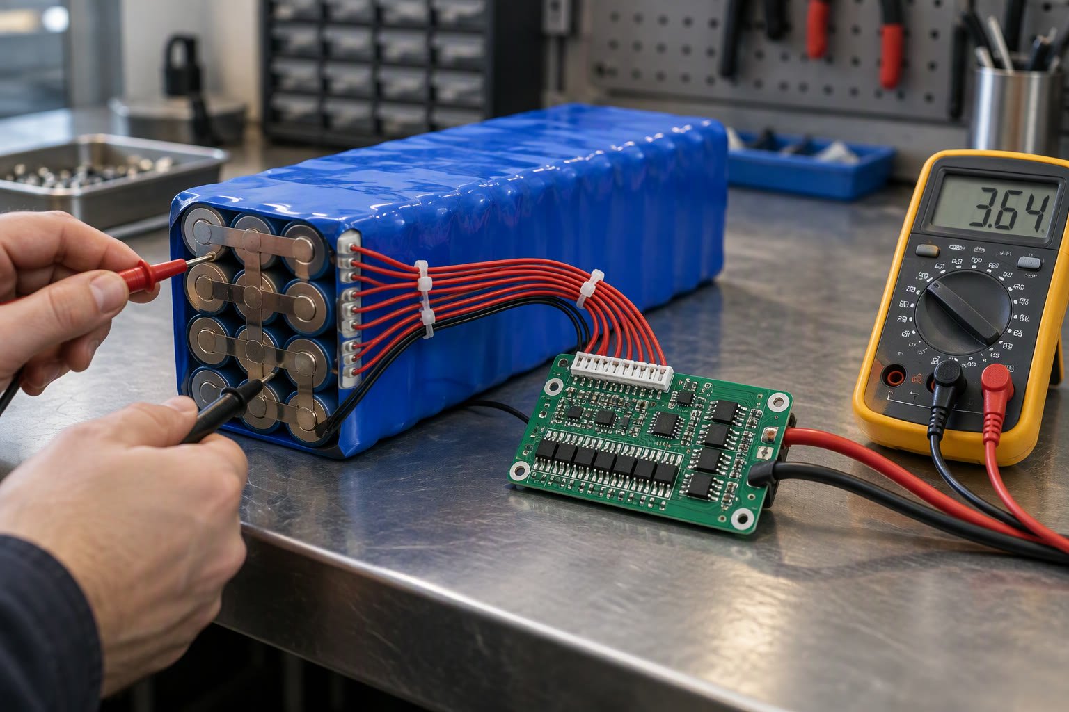
Take readings quickly and at the same charge level, because heating and discharge change the voltage while you measure. Use a known resistive load, or log both values with a current sensor such as the INA219, as in the robot battery current monitor project. Take care: do not short a lithium cell to find its resistance, and use a load rated for the power. Pulse tests of a few seconds are safer than long ones. This is general guidance, not a substitute for the cell datasheet.
Sag Calculation
The sag calculation is a single line: sag = I x R_total, where R_total includes cells, wiring, connectors and any BMS. The voltage the robot sees is then V_open – sag. Series cells add resistance, parallel cells divide it.
For a pack of S cells in series and P cells in parallel, each with resistance r:
- R_pack = S x r / P
- V_open = S x cell voltage
For an easy way to explore pack layouts and energy, use the battery pack series and parallel calculator.
Worked Example for a Robot Pack
Assumptions: a 3S2P pack of 18650 cells (3 in series, 2 in parallel, 6 cells total), each cell with an assumed internal resistance of 0.060 ohm (60 milliohm), a resting 3.8 V per cell, and an extra 0.040 ohm for wires, connectors and the BMS. The robot draws 8 A.
- Pack cell resistance = 3 x 0.060 / 2 = 0.090 ohm.
- Total resistance = 0.090 + 0.040 = 0.130 ohm.
- Open-circuit voltage = 3 x 3.8 = 11.4 V.
- Sag = 8 x 0.130 = 1.04 V.
- Voltage at the robot = 11.4 – 1.04 = 10.36 V.
- Heat lost in the pack and wiring = 8 squared x 0.130 = 64 x 0.130 = 8.32 W.
- Power drawn from the cells = 11.4 x 8 = 91.2 W, so the loss fraction is 8.32 / 91.2 = 0.0912, about 9.1 percent.
| Quantity | Value |
|---|---|
| Open-circuit voltage | 11.4 V |
| Total resistance | 0.130 ohm |
| Sag at 8 A | 1.04 V |
| Voltage under load | 10.36 V |
| Heat in pack and wiring | 8.32 W |
About 9 percent of the energy goes to heating the pack instead of the motors in this example, and at twice the current the heat is four times larger (16 A gives 256 x 0.130 = 33.28 W). Keep an eye on cell and wire temperature if you run high currents, and check the cell maker’s maximum continuous discharge rating. The 18650 battery pack page covers the pack type used here.
Cell Matching
Cell matching means building a pack from cells with similar capacity and resistance, because parallel cells share current in inverse proportion to their resistance. Take two cells in parallel carrying 8 A in total, one at 0.060 ohm and the other at 0.090 ohm.
- Current in the 0.060 ohm cell = 8 x 0.090 / (0.060 + 0.090) = 8 x 0.6 = 4.8 A.
- Current in the 0.090 ohm cell = 8 – 4.8 = 3.2 A.
- Check: 4.8 x 0.060 = 0.288 V and 3.2 x 0.090 = 0.288 V, the same voltage across both, as it must be.
The lower-resistance cell carries 50 percent more current than the other and ages faster. Avoid mixing old and new cells, brands or capacities in one pack, and check each cell’s voltage before joining them in parallel. Charging and protection rules are covered in the battery management system guide.
Effect on Runtime
Internal resistance shortens usable runtime because the electronics reach their low-voltage cutoff earlier. Suppose your system cuts off at 9.0 V at the terminals. Under the 8 A load above, the terminal voltage is the open-circuit voltage minus 1.04 V, so cutoff arrives when the open-circuit voltage is 9.0 + 1.04 = 10.04 V, which is 3.35 V per cell. A 3S cell is not empty at 3.35 V, so a share of the charge stays unused, and a lower current or lower resistance recovers some of it.
Resistance also lowers efficiency, as the 8.32 W shows. Use your own measured current when estimating runtime; the battery runtime calculator and the battery sizing calculation give a first estimate, and the robot battery guide explains cell types. More topics are in the Learn hub.
How to check this yourself
- Charge the pack fully and let it rest, then record the open-circuit voltage with a multimeter.
- Apply two loads of different current for a few seconds each, recording voltage and current at each.
- Compute R = (V1 – V2) / (I2 – I1) and repeat at a lower charge level to see how it changes.
- Predict sag at your robot’s normal current using V = I x R, then compare it with the measured voltage during real driving.
- Feel the wires and pack after a run at high current; unexpected warmth points to extra resistance.
Common mistakes
- Judging a battery by its resting voltage only, without checking under load.
- Forgetting wire, connector and BMS resistance in the total.
- Mixing cells of different age or capacity in parallel.
- Measuring voltage across the battery clips only, not at the robot’s electronics.
- Using a rated capacity and assuming it holds at high current.
Frequently asked questions
What is battery internal resistance?
It is the resistance inside a cell and its connections that opposes current flow. It makes the terminal voltage drop by current times resistance when you draw power. Low resistance means a stiffer battery that holds voltage under load. Resistance usually rises with age and in cold conditions.
How do I measure battery internal resistance at home?
Measure the terminal voltage at two different load currents, then divide the voltage difference by the current difference. For example, 11.27 V at 1 A and 10.75 V at 5 A gives 0.52 / 4 = 0.13 ohm. Use short pulses and a load rated for the power, and never short a cell.
Why does my battery voltage drop when motors start?
The motors draw a large current, and that current flowing through the battery’s internal resistance and the wiring causes a voltage drop equal to current times resistance. A pack with higher resistance, thin wires or poor connectors sags more. The voltage recovers when the load drops.
Quick checklist
- Use V = I x R with the total resistance, including wires and BMS.
- Measure resistance with two load currents, not by guessing.
- Remember series adds resistance and parallel divides it.
- Match cells by capacity, age and resistance.
- Include sag when you decide the low-voltage cutoff.
Related reading
- Battery state of charge estimation for working out how much charge remains under load.
- Ohm’s law and power calculator for quick sag and heat checks.
About the author and how this is kept accurate
Written, checked and maintained by Jignesh Panchal of Jaadu Digital. Figures in worked examples come from the stated assumptions, not from a bench test of our own. Read the editorial standard, follow the author on LinkedIn, or send a correction. Last reviewed: November 2026.