A ROS-ready robot base is a mobile chassis with wheel encoders, a motor controller that accepts velocity commands, a documented way to connect an onboard computer, and a battery you can charge safely. Check the drive type, encoder resolution, computer interface, sensor mounting points and documentation before you buy.
Key takeaways
- ROS (Robot Operating System) is a set of software tools and conventions for robots, and a ROS-ready base should accept velocity commands and report wheel odometry.
- A differential drive base steers by running its left and right wheels at different speeds.
- Encoder resolution decides how fine your odometry is, and you can calculate distance per tick from wheel size and counts per revolution.
- Good documentation and an open interface matter as much as the hardware.
Drive Type and Kinematics
The drive type is how the base moves and turns, and kinematics is the maths that links wheel speeds to robot motion. The most common beginner choice is differential drive, with two powered wheels and a caster, while other options include four-wheel skid steer, Ackermann (car-like) and mecanum bases.
Differential drive is the most widely documented in ROS tutorials, and the tools for it are widely available, so it suits a first ROS robot. Skid steer and mecanum bases work but make odometry less accurate because wheels slip. Check the drive type against your floor: smooth indoor floors suit most bases, while rougher surfaces need larger wheels and more torque.
Ask for the wheel diameter and the distance between the wheels (the wheel separation), because ROS controllers need both numbers. The ROS 2 control tutorial shows where they go in the configuration.
Encoders and Odometry
An encoder is a sensor that counts wheel rotation, and odometry is the estimate of robot position built from those counts. Without encoders, a base cannot tell ROS how far it has moved, so check that each driven wheel has one.
Here is an illustrative worked example. Assume an encoder gives 20 counts per motor revolution, a gearbox of 30 to 1, and you read both channels in a way that gives the counts per revolution as listed. Counts per wheel revolution = 20 × 30 = 600. Assume a wheel diameter of 65 mm. Circumference = π × 65 mm = 204.2 mm. Distance per count = 204.2 / 600 = 0.340 mm. So each count means about a third of a millimetre of travel.
| Item | Illustrative value | Working |
|---|---|---|
| Counts per wheel turn | 600 | 20 × 30 |
| Wheel circumference | 204.2 mm | π × 65 |
| Distance per count | 0.340 mm | 204.2 / 600 |
The counts per revolution depend on how the encoder is read, so check the datasheet and the firmware. You can try your own values in the encoder counts and wheel distance calculator. For the maths of turning counts into pose, read the differential drive odometry guide, and see the differential drive odometry project for an Arduino version.
Onboard Compute Interface
The compute interface is how the base’s motor controller talks to the onboard computer that runs ROS. Many bases use a microcontroller for motors and encoders, connected by USB serial to a single-board computer such as a Raspberry Pi, which runs ROS.
Check three things. First, the message format: a documented serial protocol or a ready ROS node that accepts velocity commands on the /cmd_vel topic and publishes odometry on /odom. Second, the computer you plan to use, and whether your ROS distribution supports its operating system and CPU type. Third, the power connection, since a single-board computer needs a clean supply that does not reset when motors start.
If the base has no ready ROS node, you can write a small bridge, as in the ROS 2 cmd_vel bridge for an Arduino differential drive project. If you are new to ROS, read the ROS 2 tutorial for beginners first.
Sensor Mounting
Sensor mounting is how easily you can fix a lidar, camera, IMU or ultrasonic sensors to the base. ROS navigation often needs a lidar placed with a clear view all around and a known position relative to the wheels.
- Look for a flat top deck with a grid of mounting holes or standard-spaced slots.
- Check that the deck is rigid enough to keep the sensor from wobbling.
- Leave space for cables and a spot for the computer and a switch.
- Ask for the CAD file or dimensions, because ROS needs the sensor position in the robot description.
A sensor with a poor mounting position causes wrong maps even when the software is correct, so measure the offsets carefully after fitting.
Battery and Charging
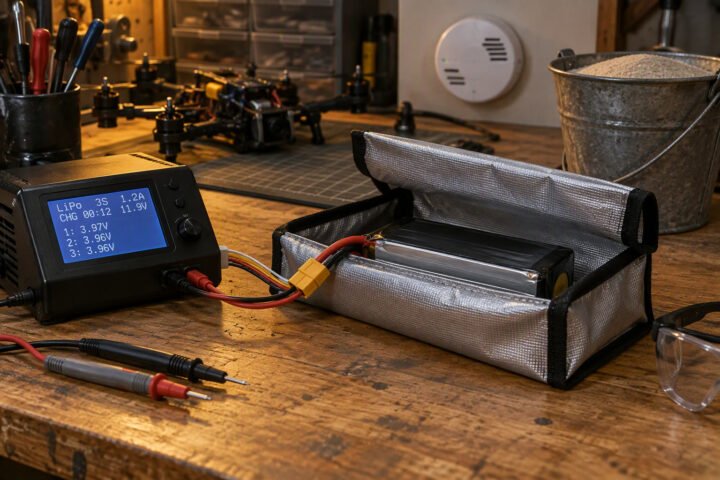
The battery powers the motors, the controller and the onboard computer, and charging is how you refill it safely. Check the battery chemistry and voltage, the capacity, and whether a proper charger and a battery protection board are included.
The computer and sensors need stable voltage, often through a regulator, while motors draw large and uneven current. A base with separate or well-filtered supplies avoids computer resets. Caution: lithium batteries can cause burns and fires if abused, so follow the maker’s charging instructions and use a suitable charger. This is general guidance, not a substitute for the battery maker’s instructions. Check the runtime claim against your own load, and use a battery runtime calculator to estimate it.
Documentation and Support
Documentation is the written material that explains how to use the base, and support is the help available when something fails. For ROS, good documentation includes a wiring diagram, the serial protocol or ROS package, the encoder and wheel numbers, and a robot description file (URDF).
Check whether the maker provides a maintained ROS 2 package, which ROS distribution it targets, and whether the code is open. Check the date of the latest update on the project page, since old packages may not build on current distributions. Look for user forums, issue trackers or tutorials you can follow. If the documentation is thin, expect to spend time reverse engineering the base.
How to check this yourself
- Find the wheel diameter, wheel separation and encoder counts per wheel revolution in the documentation.
- Compute distance per count with circumference divided by counts per revolution, and confirm it matches the maker’s numbers.
- Check that the ROS package targets the distribution and operating system you plan to install.
- Check whether the motor controller accepts velocity commands, and whether it publishes odometry or wheel counts.
- After assembly, drive the base a measured one metre with a tape measure, and compare the odometry reading with the real distance.
Common mistakes
- Buying a base with no encoders and expecting odometry.
- Assuming wheel separation does not matter, then seeing turns come out wrong.
- Choosing a base whose ROS package targets an old distribution.
- Powering the onboard computer from the same unfiltered supply as the motors.
- Mounting the lidar without measuring its offset from the wheels.
Quick checklist
- Confirm drive type, wheel diameter and wheel separation.
- Check encoder resolution and compute distance per count.
- Check the ROS package and the distribution it supports.
- Plan a clean supply for the onboard computer.
- Measure the sensor offsets after mounting.
Frequently asked questions
What makes a robot base ROS-ready?
It accepts velocity commands, usually on the cmd_vel topic, and reports wheel odometry. It also has encoders, a documented interface to an onboard computer, and ideally a maintained ROS package. Check these in the documentation before you buy.
Do I need encoders for ROS navigation?
Wheel encoders give odometry, which navigation uses to estimate motion. You can add other sensors such as an IMU or lidar to improve the estimate, but a base with encoders is the usual starting point. Check the counts per revolution, and calibrate wheel size and separation.
Can I use a Raspberry Pi with a ROS robot base?
Often yes, if its operating system and CPU type are supported by your ROS distribution. Many bases use a microcontroller for motors, connected to the Pi by USB serial. Check the maker’s documentation and the ROS distribution requirements first.
Related reading
- Wheel speed and RPM calculator: check speed targets for your wheels and motors.
- Learn hub: more explainers on ROS and robot control.
- Build hub: ROS and mobile robot projects.
About the author and how this is kept accurate
Written, checked and maintained by Jignesh Panchal of Jaadu Digital. Figures in worked examples come from the stated assumptions, not from a bench test of our own. Read the editorial standard, follow the author on LinkedIn, or send a correction. Last reviewed: November 2026.