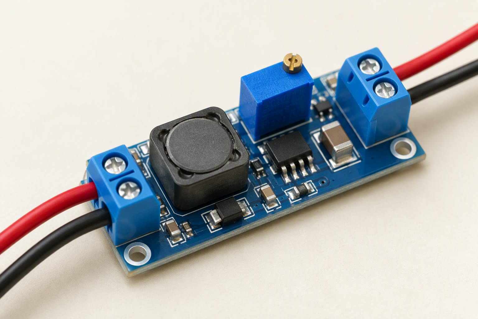
When you choose a buck converter module for a robot, check that your battery voltage sits inside its input range, that its current rating has real headroom over your load, and that its output stays quiet enough for your microcontroller. Then test it on the bench before it goes into the robot.
Key takeaways
- A buck converter module steps a higher DC voltage down to a lower one using switching, so it wastes far less heat than a linear regulator.
- A buck converter module checklist should cover input range, output current with headroom, efficiency at your actual load, ripple, and heat.
- Output power equals output voltage times output current, and input power is output power divided by efficiency.
- A module sold as 3 A may not deliver 3 A continuously without a heatsink, so plan for a lower real limit.
Input and Output Range
The input range is the span of battery voltages the module accepts, and the output range is what it can be set to. Your fully charged battery must stay below the maximum input, with margin for spikes.
A 3-cell lithium pack reaches about 12.6 V when fully charged, and a 12 V lead-acid battery can sit above 13 V while charging. Motor switching can add spikes on the supply line. Pick a module whose rated maximum input is well above that, and check the dropout: a buck converter needs the input to stay above the output by some margin, or the output falls. Check the datasheet of the chip. Common chips such as the one on the LM2596 buck converter module accept a wide input range, while compact chips like the one on the TPS62130 module have a lower maximum input. Read the listing carefully, since the board may have other limits, such as capacitor voltage ratings.
Many modules have an adjustable output with a small trimmer. Set it with a multimeter before connecting your microcontroller.
Current Rating and Headroom
Current rating is the output current the module can supply, and headroom is the safety margin between that and your real load. A common rule is to choose a module rated at least 1.5 times your expected peak load.
List the loads on the 5 V rail: the microcontroller, sensors, servos and any Wi-Fi radio. Servos and motors cause the sharpest peaks. If your measured or estimated peak is 2 A, then 2 A x 1.5 = 3 A is the suggested rating. If the module is sold as 3 A, check whether that needs a heatsink or an airflow condition. Separate rails are also worth considering: power servos from their own converter, so a servo stall does not reset the controller. The how to power a robot guide explains rail planning.
Efficiency at your load
Efficiency is output power divided by input power, and it changes with load and input voltage. A listing’s headline figure usually applies at one favourable point.
Worked example, with assumed numbers: input 12 V, output 5 V at 2 A.
- Output power = 5 V x 2 A = 10 W.
- At an assumed 90 percent efficiency, input power = 10 W / 0.90 = 11.11 W.
- Heat lost = 11.11 W – 10 W = 1.11 W.
- Input current at 12 V = 11.11 W / 12 V = 0.926 A.
- At an assumed 80 percent efficiency, input power = 10 W / 0.80 = 12.5 W and heat lost = 2.5 W.
For comparison, a linear regulator dropping 12 V to 5 V at 2 A wastes (12 – 5) x 2 = 14 W as heat, which is why robots use switching converters. A difference of ten points of efficiency changes battery life and heating, so test it. The 12 V to 5 V buck converter guide shows how this fits a robot.
| Assumed efficiency | Input power for 10 W out | Heat in module |
|---|---|---|
| 90 percent | 11.11 W | 1.11 W |
| 80 percent | 12.5 W | 2.5 W |
| 70 percent | 14.29 W | 4.29 W |
Ripple and Noise
Ripple is the small, fast variation left on the output after switching, and noise includes spikes. Too much can upset analog sensors, radios and microcontroller resets.
Cheap modules often have small output capacitors. If your ADC readings jump when a motor starts, suspect the supply. Adding a capacitor near the load and keeping wires short can help. Measure ripple with an oscilloscope if you can, and read the numbers as a comparison, not as a certificate. Use a short ground lead on the probe, because a long lead adds its own pickup.
Heat and Layout
Heat is the power wasted inside the module, and layout is how it is placed in your robot. Hot modules can fail early, and some derate current as they warm.
Mount the module where air can pass, away from batteries. Use thick wire on the high-current side, and keep the input and output leads apart. Check the inductor: a small one can saturate near its limit and cause trouble. After a few minutes under load, touch the chip lightly or use a thermometer to compare. Warm is normal, while a burn-your-finger temperature means you need a bigger module or a heatsink. Lithium packs need correct protection; this is general guidance, not a substitute for the maker’s instructions. See the robot battery guide.
Testing on the Bench
Bench testing means running the module with a dummy load before it goes into the robot. It costs little and protects your controller.
Set the output voltage first with nothing connected. Then add a resistor or a known load and measure the output under current. Finally, connect it into the ESP32 robot car setup or similar, and watch for resets when motors start.
How to check this yourself
- Read the chip’s datasheet for maximum input voltage, rated current and switching frequency, and compare with the listing.
- Connect the input to your supply, set the output with a multimeter, and record it with no load.
- Add a power resistor sized for roughly your expected current, using the Ohm’s law relationship, and record the output voltage and input current.
- Calculate efficiency as output power divided by input power for two or three loads.
- Run the load for ten minutes and check the temperature of the inductor and chip.
Common mistakes
- Trusting the rated current on the listing with no heatsink or airflow.
- Setting the output with the robot already connected.
- Running servos and the microcontroller from the same small module.
- Forgetting that a full battery voltage is higher than its label.
Quick checklist
- Maximum input voltage comfortably above a fully charged battery.
- Rated current at least 1.5 times your peak load.
- Efficiency estimated at your own load, not the headline figure.
- Output voltage set and checked before connecting the controller.
- Temperature checked after a ten-minute load test.
Frequently asked questions
Is a buck converter better than a linear regulator for robots?
For battery robots it usually wastes much less energy. A linear regulator turns the voltage difference into heat, so 12 V to 5 V at 2 A wastes 14 W. A buck converter wastes far less. Linear regulators are still useful for very quiet, low-current circuits.
What current rating should my buck converter have?
A common rule is at least 1.5 times your expected peak load. If your 5 V rail peaks at 2 A, look for a 3 A module and check whether it needs a heatsink. Add a separate converter for servos if they stall.
Why does my robot reset when the motors start?
Motor starts cause voltage dips and spikes on the shared supply. The converter may reach its current limit, or the input may sag. Use a larger module, add capacitors near the controller, give motors a separate rail, and check the battery’s ability to supply current.
Related reading
- Obstacle avoiding robot with Arduino, a project with a regulated 5 V rail.
- Ohm’s law and power calculator, for sizing a test load.
- Robotics tools hub, for more calculators.
- LiPo Charger Module: What to Check Before Buying
- LoRa Modules for Farm Robots: What to Check
- Voice Recognition Modules for Robots: Offline or Cloud
About the author and how this is kept accurate
Written, checked and maintained by Jignesh Panchal of Jaadu Digital. Figures in worked examples come from the stated assumptions, not from a bench test of our own. Read the editorial standard, follow the author on LinkedIn, or send a correction. Last reviewed: November 2026.